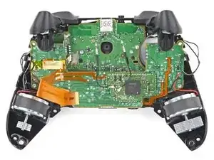
Introduction

Follow this guide to replace the headset jack in your Scuf Instinct Pro Xbox controller.

You may need to replace the headset jack if there's no audio output or if the audio is fuzzy, cuts in and out, or is one-sided. Replacing the headset jack will also fix a loose connection.

Before replacing the audio jack, test your headphones with another device to make sure the problem isn't with the headphones themselves.

  1. 5OkDhPDMtblly2hJ
    5OkDhPDMtblly2hJ
    XWguLyDlcAWJXAwe
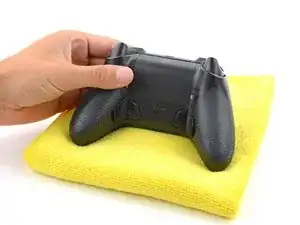
    • Unplug all cables from your controller before starting.

    • Completely power off your controller.

    • Due to the controller’s odd shape, it can be helpful to stabilize it as you work. To prevent damage, consider laying it on a soft surface like a cloth or towel.

  2. grHqonDk3VFuVbNF
    grHqonDk3VFuVbNF
    wouLFNuxACh2S1Wf
    n2PXvosWOaAsS5gZ
    • Magnets secure the faceplace to the midframe.

    • Lift the top edge of the faceplate to release the magnets securing it.

    • Remove the faceplate.

  3. hyRWWXIRLvrHuSQL
    hyRWWXIRLvrHuSQL
    ZbCNDRrCGhoiIVGC
    • Weak magnets and two clips along the bottom edge secure the battery cover to the controller.

    • Slide the battery cover away from the controller to remove it.

  4. anhICJF3JAFjokMG
    anhICJF3JAFjokMG
    uYrpCINQBCVJSqBJ
    wdMWQabbNBOVNiEF
    • If your batteries are starting to corrode, clean the contacts and replace the batteries.

    • Use your fingers to remove the batteries.

    • During reassembly, insert the batteries so their positive (+) and negative () ends match up with the markings on the battery contacts.

  5. nAbqyikSyoGLOIrb
    nAbqyikSyoGLOIrb
    DcIHNSrbj1pCoUam
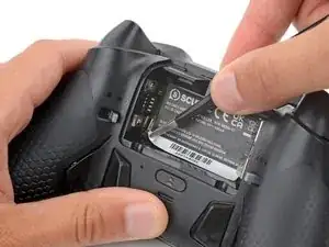
    • The sticker in the battery recess hides a back cover screw.

    • If you don't care about damaging the sticker, you can puncture through the center and skip the next step.

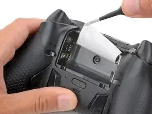
    • Use a hair dryer to heat the sticker and soften the adhesive securing it.

    • The sticker can be peeled without heating, but you risk tearing it.

  6. OGWoOKOuU32v2hXb
    OGWoOKOuU32v2hXb
    I3E5ejKIfqYVh5qH
    egxoVafpcqmojEou
    • Use the point of a spudger to push up a corner of the sticker until you can grab it with a pair of blunt nose tweezers.

    • Use your tweezers to peel up the sticker until the back cover screw is accessible.

  7. usZ6GVsD4ZmmZEy1
    usZ6GVsD4ZmmZEy1
    SGMgj5NljxikbFQh
    vMbY1KF1sp5gCrZq
    • Throughout this repair, keep track of each screw and make sure it goes back exactly where it came from.

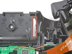
    • Use a T8 Torx screwdriver to remove five 9.3 mm‑long screws securing the midframe:

    • One back cover screw

    • Four screws on top of the midframe

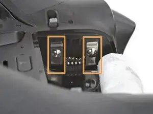
    • Use a T6 Torx screwdriver to remove the two 9.3 mm‑long screws securing the midframe.

  8. 1OZXAgc3nXRBdfXa
    1OZXAgc3nXRBdfXa
    CxHYPQSdD6EIIFjY
    1gLapEMOHCJHEJhi
    • Plastic clips secure the bottom edge of the midframe.

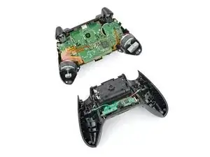
    • Insert the flat end of a spudger between the bottom edge of the midframe and back cover.

    • Pry the midframe up with the spudger to release the clips.

    • Continue prying along the bottom edge to release the remaining clips.

    • Don't try to remove the midframe from the back cover yet—a delicate ribbon cable connects them.

  9. Z3AirmDZVD2SgSqj
    Z3AirmDZVD2SgSqj
    ZSLPuvcLVL4rvBdR
    UmxecefAqNFAwQnE
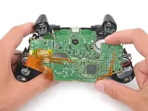
    • Put a box or a stack of books to the right of the controller so you can prop up the midframe while disconnecting its ribbon cable.

    • Secure the back cover with one hand, and use your other hand to grip the midframe's left edge.

    • Lift the midframe and rotate it over the right edge of the back cover, so the midframe's right edge is on your workspace.

    • Prop the midframe up, being careful not to strain the ribbon cable.

  10. 1vQiclLYfQdj2Io6
    1vQiclLYfQdj2Io6
    PnQZZO1B3CCQYjqI
    urnvPfTZR1VSESyY
    • During reassembly:

    • Guide the battery connectors on the midframe through their slot in the back cover.

    • Make sure the contacts slide into their grooves in the battery recess. If they aren't in the correct spot, the controller won't receive power.

  11. myeAySa4KWvoPjIX
    myeAySa4KWvoPjIX
    ihvxVtTbecGDLqSi
    FBB2mYjV2LT6yRcS
    • A very small rubber grommet secures the midframe's ribbon cable to a post on the right side of the back cover.

    • Use blunt nose tweezers to remove the grommet—don't lose it!

  12. Qa1erEUClJCRsF56
    Qa1erEUClJCRsF56
    5XicudyuHHBQ1vZw
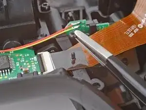
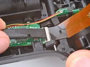
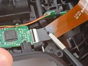
    • Use the flat end of a spudger or a clean fingernail to lift the hinged locking flap on the midframe cable ZIF connector.

  13. Trp325IdcEqi2uoD
    Trp325IdcEqi2uoD
    yvfmQNMlSUkQcQqZ
    vW31enFIv3v3wCPl
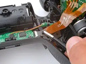
    • Use blunt nose tweezers to grip the black pull tab on the midframe cable.

    • Lift the midframe cable off its post and pull it straight out of its socket.

  14. fDufFLpIndrjKXDy
    • Remove the midframe.

  15. 3xVhRLMjIdnCc3mC
    3xVhRLMjIdnCc3mC
    3IgDnMRcFg3cAHJL
    QxMXH2dkSHQCwneF
    • The top of the USB‑C port cover is secured with a pair of plastic arms. The bottom is secured with plastic clips.

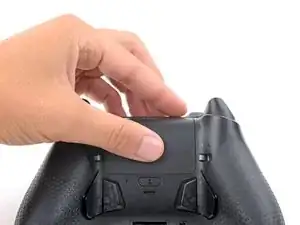
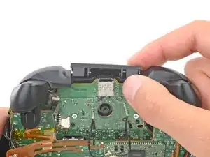
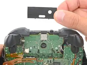
    • Rotate the underside of the USB‑C port cover up and away from the controller to release the bottom clips.

    • Unhook the plastic arms and remove the cover.

    • During reassembly:

    • Hook the ends of the USB‑C cover's arms into their slots on either side of the Xbox button.

    • Rotate the cover downward until the bottom clips engage and the cover is flush with the bumpers.

  16. HarFbYTMN5AKOTOW
    HarFbYTMN5AKOTOW
    ptZIOJKPVIdc3wGN
    aQWTPHUWrWeWCVYd
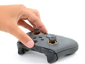
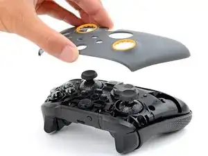
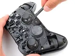
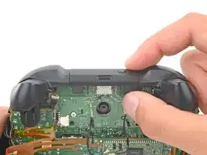
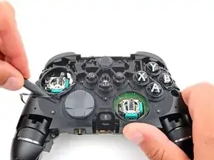
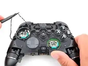
    • Firmly secure the controller with one hand, and use your other hand to lift the thumbstick covers straight off their modules.

    • This requires significant force. If you're having trouble, try wiggling the cover to help loosen it.

    • To install a thumbstick cover:

    • Place and rotate the cover on its module until it slides into place.

    • Firmly press down on the cover until it snaps into place or bottoms out.

  17. AxfJQHd3BbMTgTKr
    AxfJQHd3BbMTgTKr
    benXV2FgRJNdWJQX
    BCcvIRVWR5WC3k5G
    • Use the point of a spudger to guide the trigger rumble motor wires out of their clips on the midframe.

  18. XQEwN5vUELO5IJaW
    XQEwN5vUELO5IJaW
    rxAedkYNbaqRwXIu
    pN5D2Qlck1gJDmpK
    • Be very careful not to scrape off or damage any surface mounted components during this step.

    • Flip your controller over.

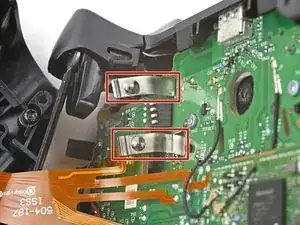
    • Insert an arm of your angled tweezers under the metal neck of one of the coaxial connectors and lift straight up to disconnect it from the thumbstick board.

    • Disconnect the other connector.

    • To reconnect coaxial connectors, hold each one in place over its socket and press down with the flat end of your spudger. The connector will snap into place.

  19. YLPALSGc1oXNaV3A
    YLPALSGc1oXNaV3A
    wEi1mp6BxiLSitIL
    • Use a T6 Torx screwdriver to remove the two 7 mm‑long screws securing the thumbstick board.

  20. WUjQrFLRxrrcgQ16
    WUjQrFLRxrrcgQ16
    uBPMFLOVIb1mFmO6
    SDDYcQIixrewk6Sh
    • The thumbstick and charging boards are connected with a socket.

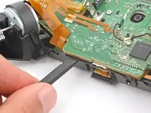
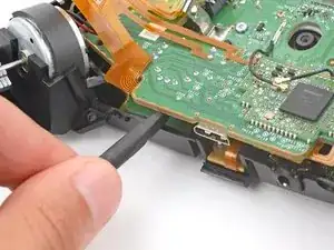
    • Insert the flat end of a spudger between the bottom edge of the thumbstick board and midframe.

    • Twist the spudger to separate the boards.

    • During reassembly, gently push the thumbstick board onto the charging board until you feel the plug slide into the socket.

  21. cjId5wCUZGDOEQOr
    cjId5wCUZGDOEQOr
    jsaiFacKJc4j2AUq
    drwo12KXrdTZQit5
    • Delicate wires are soldered to the outer edges of the thumbstick board. Be very careful during this step to avoid tearing the wires from the board.

    • Gently lift the thumbstick board and reposition it over the bottom of the midframe so the board is standing upright.

    • The headset jack may fall out, as nothing is securing it to the charging board anymore.

    • During reassembly:

    • Use the alignment posts to orient the board.

    • When lowering the board into place, make sure the black antenna cables don't get stuck under the board.

  22. skcuwbBNjRNYtJxE
    skcuwbBNjRNYtJxE
    2YAKgLcJYMSEsBAr
    DdeRH6qRAtkCburG
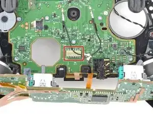
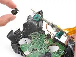
    • Remove the headset jack from the bottom right corner of the charging board.

    • During reassembly:

    • Make sure the headset jack is properly oriented, with the socket on the bottom edge of the charging board and the gold contacts facing up.

Conclusion

To reassemble your device, follow these instructions in reverse order.

Take your e-waste to an R2 or e-Stewards certified recycler.

Repair didn’t go as planned? Try some basic troubleshooting, or ask our Answers community for help.

Spencer Day

Member since: 14/09/22

88286 Reputation

0 comments