Introduction
In this guide, I am showing how with the use of a uncurled paperclip you can easily remove and replace the LED strips on the Samsung UE40MU5120KXXU TV and other TV models and brands that use this uniquie type of clasp fitting.
-
-
Before you follow this guide, make sure you have verified the parts you need and in my case have space set aside to safely store the LCD screen pannel safely and the TV in a dismantled state. As only upon dismanteling the TV, are you able to see the LED's specific serial codes.
-
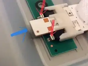
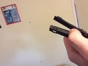
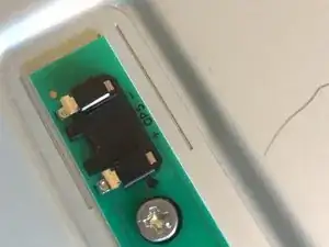
Shown here is how the LED strip is removed, it's tricky as you need to depress the two tiny tabs shown here with the two directional RED arrows. With the Blue Arrow indecating the direction of push once the two are depressed. Due to the difficulty, you should use a unwond paperclip to depress the contacts.
-
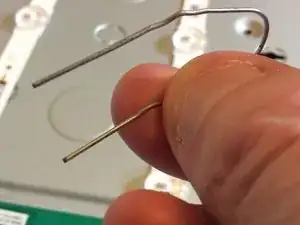
With your trusty paperclip shaped like this, your ready to start Operation Papercip. I dont have a teardown guide, but am reversing the reasemble guide instead.
-
-
-
Step 1, get yourself some ziplock bags, some tape recomended by iFixit to hold the circuit to the screen and a lot of patiance. This dismantaling and reasembly is like a puzzlebox. I got confused rebuilding it.
-
With the TV placed screen down on a flat surcace, with a towel sheet or on the bed in my case. You are now looking at the back of the TV. You may have the TV stand on the TV. If you dont skip this part. If you do, there are 4 screws to be removed. Then the snand slides in a downwards direction to remove. Place these in the ziplock bag!
-
There are 14 screws to remove. These like the TV stand screws are all the same. Remove them and place in a zip lock bag. Place the stands screws in that bag too. so you know what goes where.
-
-
-
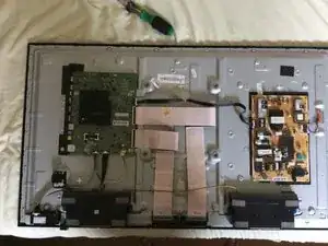
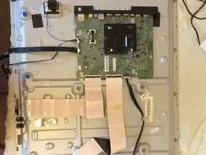
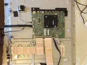
With the rear pannel's 14 screws removed. Take the back off carefully. take note of the infer red lense on the rear bottom left corner. Once removed you will see this image. The image is rotated clockwise, from where it should be, so the bottom is now the left side of the image. there are 4 things to unclip.
-
The first one is the speakers, not in this picture, as I forgot to put them back in! In the image, you see the green circuit board. at the bottom of the circuit board, you see two ribbons. keep tehse connected to the board, and unplug the oteer ends from the missing screen board connectors.
-
In this second image, you can see the ribon cables connected. Be super careful unclipping these. They are fragile and you need to use a splunger to flick up the black connector. This was a stressful task for me, as one wrong move and the screen will stop working. Take it slowly and if you need to, remove from the main board first.
-
-
-
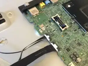
Start by removing these 2 (The speakers connector at the bottom right is already removed) connectors. There is a small tab at the top you need to depress. which is located on the cable side and lifts the clasp at the front to remove. These are easy to remove, so if it's not budging, check your releasing the clasp.
-
There are in total 4 of these clasps to remove. The speakers that you can fully remove. These are held in place by 4 blue plugs. they do remove with a bt of force from the metal plate. So remove them after unplugging. Re-insert when assembing!
-
Withe annother connected here to the rear control interface, that allows you to navigate on the screen. Place the speakers to the side and place these two cabled things in a bag. Take a picture of teh back before removing these, as I ended up taping one to the inside as I dont remember where it belonged previously.
-
-
-
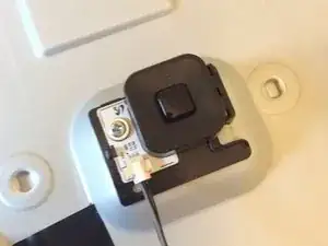
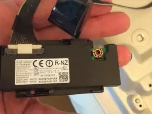
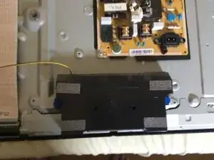
This is the componant I had no clue where it was meant to go. the R-NZ, which I believe is the Samsung android device! Here it is shown attached near the speaker. Just opened the back to show it!
-
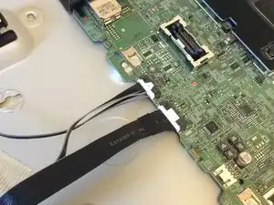
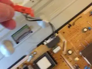
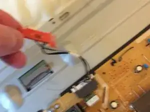
Before you continue furthe, unplug the orange connector shown here. this powers the LED strip. You will need to plug in this and the previously unplugged items shown in the first picture to test the LED strips after asemble. or if you want to test before hand. You wont need the LCD screen to be reconected till you have reasembled the frame.
-
The speaker in this image is shown connected, so remve the yellow connector.
-
-
-
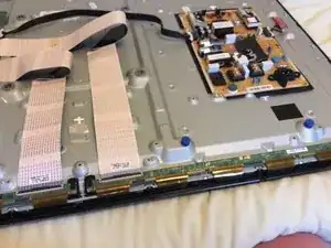
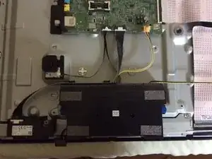
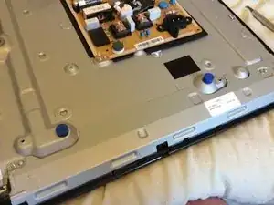
Behind the pannel shown here in these two images is teh cover for the screens driver boards and ribon connectors. The last image is of the TV without the frame, showing the ribons. These are clipped in place and delicate.
-
So start off removing the 4 screws holding this single pannel in place. place the 4 screws in a zip lock bag and place the TV housing bags in this one. Remove the place and take extra care doing this. Disconnect the aforementioned ribons here, as you can hold them more securely.
-
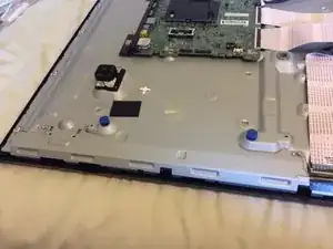
After the ribbon connectors have been removed. you will see 4 fastening clips holding these boards connected directly to the TV in place. Leave them in place! Then rotate to the screen up position.
-
-
-
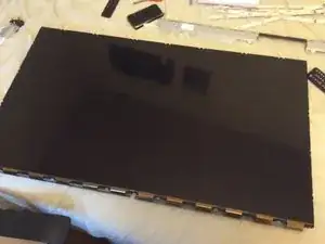
This in my opinion is very tricky, removing the outer frame from the screen. Warning!!! The LCD panel rests on a support frame, not on the lenses and plastic disfusers. So carefully with a spludger, work around to release the frame. I ended up using some force on the edge with the TV on it's side to get leverage.
-
In the end the top right and left corners budged and I was finally able to release the frame with a lot of hassle. The pro chanels make it look easy, but this has 3 layers of clasps. Designed by a sadist, given the complxity. once the top frame is released, release the boards to the LCD panel and carefully place it somewhere safe.
-
I kept the LCD pannel in this top frame, but carefully packed the ribbon as damaging that and it's game over.
-
-
-
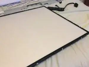
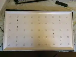
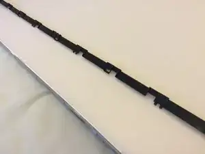
The first image is how the TV should look now. The 3rd is before I realised I messed up and these needed to be installed before teh screen! The long strips are not the same, with one showing sloaping groves where the ribons slide over. Mark this with a wrapped elastic band for later. before storing these together.
-
These black strips hold the (1) Top sheet, then (2) the magnifying frinell lense, then (3) the diffuser lens, in that order. Place a easy remove sticker say in the bottom left corner, to help you know the right order.
-
Removing these 4 black strips, and the 3 sheets, reveals a 3rd layer of white plastic panels. the long and the short panels are fit specific, so placing a rubber band arround the bottom one before bundelling together is a good idea.
-
-
-
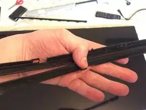
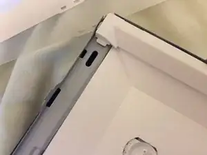
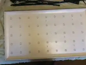
When removing the White frame, start on the sides. As you can see here, the lond sides hook under the side panels. This then presents you with the white plastic paper sheet.
-
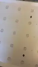
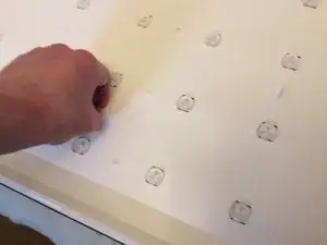
The white plastic sheet is held in place with these irregularly placed clasps. if the clasp is horizontal it's locked, if it's vertical it's unlocked.
-
once removed, you can carefully remove the plastic sheet taking care of the domes. With the orange conncetor unplugged, you will avoid the mistake I made and avoid an electric shock.
-
-
-
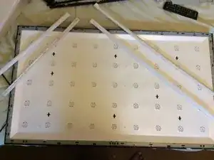
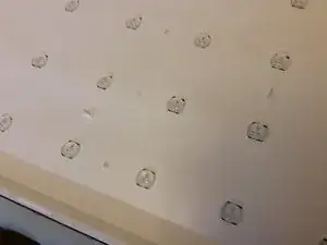
Shown here is the irregular pattern of the claps.
-
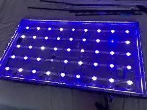
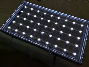
after removing the white sheet carfully, you should have all the domes visable and the strips presant. Iyou want to be sure it's the LED strips. You can plug in the IR connector and the Android device and the Orange conector. Placing the back of the TV on the back and plugging in the TV and turning it on.
-
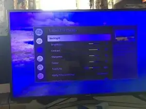
This will likely produce the same blue LED lights shown here. With when off the strips show as such. You must disconnect the orange connector afterwards and the leads to the mains. However. if your seeing a blue screen and clouds. This is likely the cause. So I wouldent bother.
-
-
-
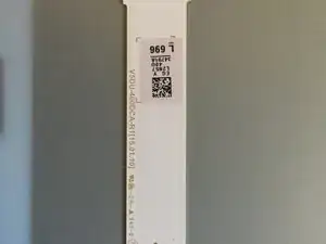
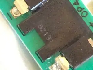
When looking closely at the LED strips, the code you are looking for is next to the sticker shown here. VSDU-400DCA-R1 & VSDU-400DCB-R1. YOU should check here that these are the parts your ordering. I waited a week for the correct parts to arrive .
-
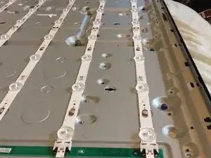
Looking down the 5 colloms, consisting of two joined together strips. You will see a single screw. Untighten this, but dont remove.
-
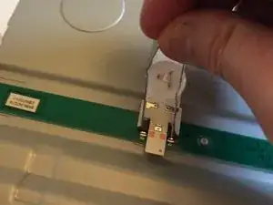
So in order to replace the strips, you need to depress these two levers that release the clasps that hold the connector in place. Get yourself a paperclip or plastic tool that works in the same fashion to do this.
-
-
-
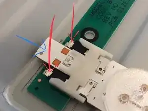
So in order to remove these strips, you push down with your tool, so your depressing in the direction of teh red arrows, to push down the leavers to release the clasp holding the light strip in place.
-
You then apply force in the Blue arrows direction to release the strip. This allows you to both remove the old LED strips and with a bit of gentle effort install the new strips.
-
Be careful inserting the new strips, you might want to connect the two halfs together first of all, as I did or one at a time. Make sure to as you push towards the connector this time push down on the strip where teh clasps are, and on the white part so the pins lock into place correctly.
-
-
-
After reconecting the new LED strips and re-tightening the screw. Ensuring the strips are securely fastened. Turn the display over and conncet the (1) Orange connector. The (2) Controler and Infer Red sensor and (3) the Android deviceseen connected in image 3.
-
Now place the back loosely onto the rear casing and then plug in the mains power lead. This is to ensure your not getting a electric shock. So from the front only the LED's are visable.
-
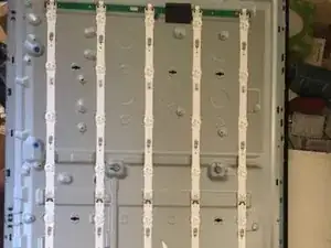
With the remote, push the power on button. after a few seconds you should see the LED's fire up and look like this picture and not blue like previousy. If they are like this. turn off the TV, unplug it and start the reasemble process.
-
-
-
Start by looking carefully where the clasp hole are located. once again make sure this is correect before fastening.
-
Next as like in the video gently run your fingers either side of the LED strip domes to ensure the sheet is tucked under the domes.
-
-
-
As a reminder these clasp points are in an irregular pattern. As shown here in the first image. Now use the locking clasps to lock the sheet in place. Horizontal orientation is locked and vertical is unlocked.
-
-
-
Now reasemble the White plastic frame. You can remove the bottom piece with the marker, a wrapped elastic band and place it at the bottom. Then the top panel. Locking that is with the side frames.
-
Next take the difuser layer (thicker plastic, removing the marker sticker, that shows the correct arrangement. So the sticker is in the bottom left corner. And lay the frinell lense then the top layer.
-
At this point now, you have removed the stickers and or markers, and are ready to install the black frame the LCD panel rests upon.
-
-
-
Take a moment to look at the Black strips, the middle image shows the bottom strip. Since you have unplugged the TV from the mains, but have not disconnected the wires, lifting up the TV you can tell if your looking at the Top or bottom as the mains cable locks the orientation.
-
The bottom strip has nice sloped groves in it whilst the top doesent. These two long strips are installed first. followed by the side strips.
-
Pay extra attention to this part. There should be a tiny recess the LCD pannel fit's into all arround. ensure this is smooth before the next steps. This should lock this section in place. Now flip the screen over and unplug the mains power lead. then remove the TV from the back. As the next part is tricky.
-
-
-
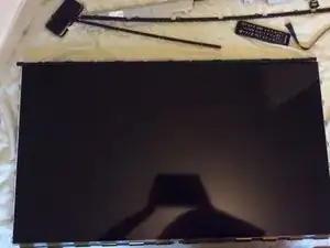
After removing the back casing, then rotating the screen back to the screen up facing. Your going to carefully put the LED screen back into the panel. The screen fit's snuggly into the groves like the 1st image. start from the bottom up, ensure the botton circuit strips are not trapped under the LCD panel.
-
Having done teh above, it's really easy to get those strips under teh LCD pannel. It's also hard to remove them because of the way the pannel is designed. So starting at the bottom first is the best way to ensure theser not trapped.
-
Once it's been aligned so it feels almost flush, do a last bit of alignment and ensure the connector strips at the bottom are not tangled up. Some people tape the conncetor to the screen to avoid this.
-
Carefully tip up from the bottom the screen with the LCD panel in the groves. Then slip the connectors under the clips to hold them in place safely for the next step. Before lowering the screen down.
-
Now carefully after checking the LCD pannel is still in the groves and has not slipped out. Get the outer frame and carefully slip and click it back into place. locking the LCD pannel safely and securely.
-
Flip the screen arround, to the cirecuit boards on the back.
-
-
-
Reconect the ribbon strips to the LCD pannel conncetors. there is a bit of clear plastci to help you aling the ribbon into the connector, ensure teh black lock is in the up position and it should look like the first image when it's correctly inserted. fold down the black connector to lock in place. Do this for both.
-
If you have disconnected from the main board reconect to teh board like shown in the first image.
-
Since the connectors should now be clipped in place. take out of the zip lock bag the 4 silver screws and the bag of the other screws. Placing the 4 screws, one each in the pictured locations to hold the pannel in place. tehre is an alignment pin to help ensure the screw is positioned correctly.
-
-
-
The first image shows the ibbon layout if your unsure at this point.
-
Plug in the speakers shown here. The one with a cable connecting to the other speaker goes on the right side of teh board. pushing in the blue plugs if you have removed it this way, or reclip. I removed the plugs to reinstall the speakers.
-
Now plug in the left side speaker. this has the yellow conector that clips into the main board.
-
At this point ensure that all the connectors are plugged in. (1) the controller + inferred recever. this connector has a red dot on the part that connects to the main board & a small connector to the controlleras seen in the first image. (2) The android device that has R-NZ written on it. (3) the yellow speaker.
-
(4) Orange power connector to the LED strips. (5) The LCD pannels connector ribbons are properly connected in and are not wonkey.
-
Place the rear casing over the back of the TV, ensuring the infer red sensore is placed in the position shown below the R-NZ in the 3rd image. Plug in the mains lead and flip over to the screen side.
-
-
-
Plug in the TV to the mains and use the power on button to turn on the TV.
-
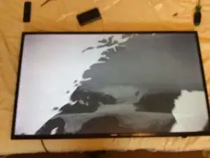
despite the aweful TV image shown here , that came up as I turned on the TV onto youtube. This happeded to be a random image and the TV was perfectly fine. The images I was going to put up are not working.
-
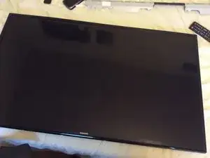
So at this point, you should see the screen not looking blue and cloudy like the second image and after entering the sources tab. and openimg say youtube. Which is where this first image came from and had me worried for a moment that I had damaged the screen. If it's all ok from this point. Once again unplug the TV. Then flip onto back.
-
-
-
Now teh TV is on it's back. open the zip lock bag, remove the other bag and take out the 14 screws.
-
You need to screw in the 14 screws into the holes provided to lock the casing into the screen.
-
Once the casing is sealed with the 14 screws. if you have the TV stand to install. Remove the four screws from the final zip lock bag. slide the TV stand upwards into the casings channel proovided and screw in the 4 screws to lock the stand in place.
-
Now it's time to plug the TV in oncxe more and pat yourself on the back for fixing your TV. I hope you found this helpful.
-


The disasembly and reasembly was tricky. With figuring out how to detach the LED strips being the trickiest part. If you know you have the correct parts, the whole job should take an hour. In my case it took a good couple of hours, as I made a bunch of mistakes which I explain how to avoid in the guide.