Introduction
This guide will teach you how to repair the speakers on this device.
-
-
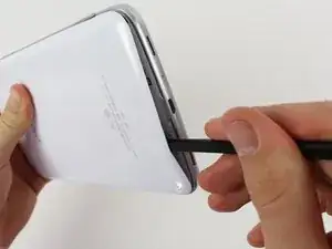
To begin working on your repair, turn your device over and open the micro SD slot, as shown in the first picture.
-
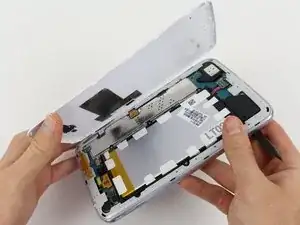
Using the flat part of the spudger, begin pushing it between the white backing and the SD slot. Continue to pry off the white backing until you hear several clicks and see the white backing lift up, as shown in the second picture.
-
Continue to pry off the white backing around the device, as shown in the third picture.
-
-
-
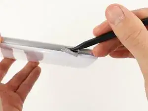
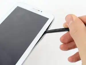
To remove the silver siding, begin by pushing the spudger between the frame and the screen, as shown in the first picture.
-
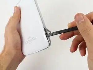
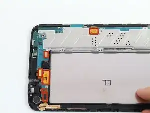
Do this until you see the silver siding begin to lift up. Continue doing this around the edges of the device, as shown in the second picture.
-
Once you silver siding is loose all around the device, remove it carefully with your hand as shown in the third picture.
-
-
-
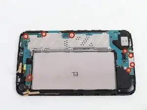
Begin by removing the four designated 1.33x2.00 mm Phillips screws with the screwdriver, as shown in the first picture.
-
Once the screws are removed, use a pair of tweezers or the spudger to remove the battery connector.
-
Pull the battery connector up as shown in the second picture.
-
Once the battery connector is removed, you can remove the battery using the spudger as shown in the third picture.
-
-
-
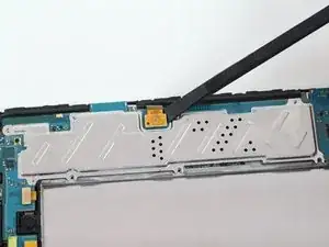
First, Remove eight 1.33x2.00mm Phillip screws.
-
Once all the screws are removed, remove the motherboard using the tweezers.
-
Once the motherboard is removed, your device should look like the device in the third picture.
-
-
-
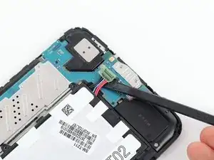
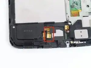
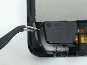
To begin removing the right speaker, lift the speaker wire with a screwdriver or spudger.
-
Make sure to lift the wire up until the glued parts of the wire are completely separated from the device.
-
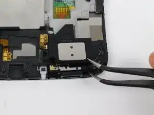
After carefully removing the speaker flat-topped connector ,remove the 1.33x2.00mm Phillps screw, as shown in the third picture.
-
-
-
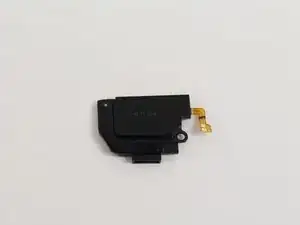
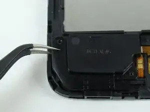
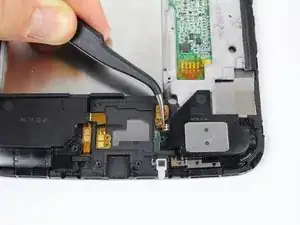
To remove the left speaker, begin by removing the speaker wire, as shown in the first picture.
-
Once the connection has been released, use your Spudger or tweezer to lift the speaker up, as shown in the second and third pictures.
-


To reassemble your device, follow these instructions in reverse order.