Introduction
Follow this guide to replace the screen and battery assembly in your Samsung Galaxy S22.
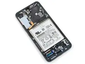
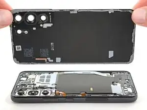
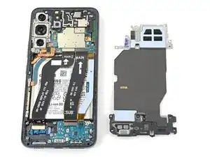
This guide is written for the screen and battery assembly. The assembly consists of the screen, battery, and frame together in one part. Be sure you have the right part before you begin the repair.
Note: Retaining water resistance after the repair will depend on how well you reapply the adhesive, but your device will lose its IP (Ingress Protection) rating.
-
-
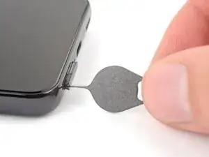
Insert a SIM eject tool, bit, or straightened paper clip into the SIM card tray hole on the bottom edge of the phone.
-
Press the SIM eject tool into the SIM card tray hole to eject the SIM card tray.
-
Remove the SIM card tray.
-
-
-
While you wait for the adhesive to soften, note the following:
-
There's adhesive securing the back cover around the perimeter of the frame.
-
-
-
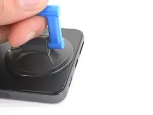
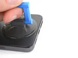
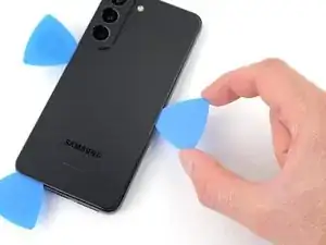
Apply a suction handle to the back cover, as close to the bottom edge as possible.
-
Pull up on the suction handle with strong, steady force to create a gap between the cover and the frame.
-
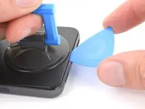
Insert an opening pick into the gap.
-
-
-
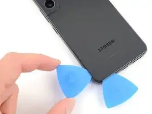
Slide the pick back and forth along the bottom edge to slice through the adhesive.
-
Leave the pick inserted in the bottom left corner to prevent the adhesive from resealing.
-
-
-
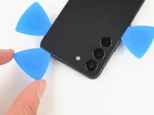
Insert a second opening pick at the bottom left corner.
-
Slide the pick to the bottom of the camera bezel to slice the left adhesive.
-
Leave the pick in to prevent the adhesive from resealing.
-
-
-
Insert a third opening pick at the bottom right corner.
-
Slide the pick to the top right corner to slice the adhesive.
-
Leave the pick in the top right corner to prevent the adhesive from resealing.
-
-
-
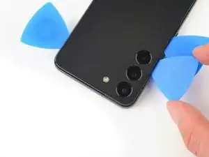
Insert an opening pick in the gap at the top right edge.
-
Slide the pick across the top edge and around the top left corner to slice the remaining adhesive.
-
-
-
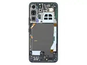
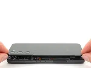
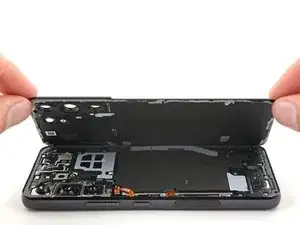
Grab and remove the back cover.
-
This is a good point to power on your phone and test all functions before sealing it up. Be sure to power your phone back down completely before you continue working.
-
Remove any adhesive chunks with a pair of tweezers or your fingers. Apply heat if you're having trouble separating the adhesive.
-
To apply new adhesive, follow this guide.
-
-
-
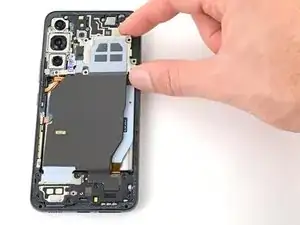
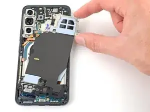
Use the pointed end of a spudger to pry and disconnect the wireless charging coil from the motherboard.
-
-
-
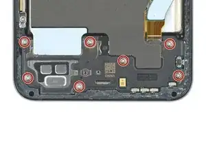
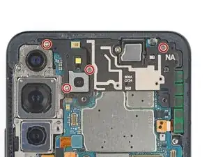
Use your Phillips screwdriver to remove the six 3.5 mm-long screws securing the wireless charging coil.
-
-
-
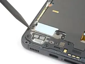
Insert the pointed end of your spudger between the upper left corner of the loudspeaker and the frame.
-
Pry up to unclip the loudspeaker from the frame.
-
-
-
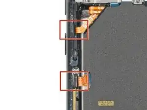
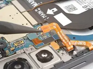
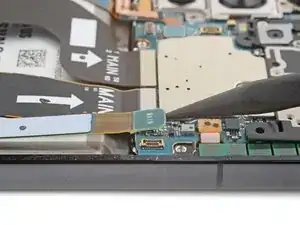
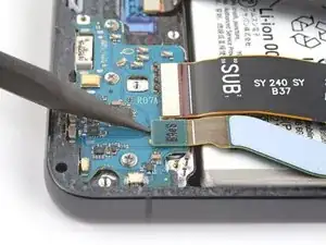
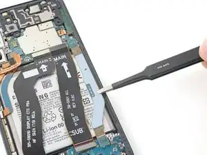
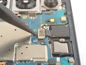
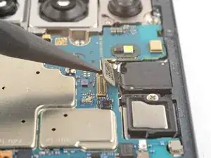
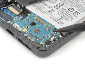
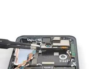
Use the pointed end of your spudger to pry up and disconnect both interconnect cables from the motherboard.
-
-
-
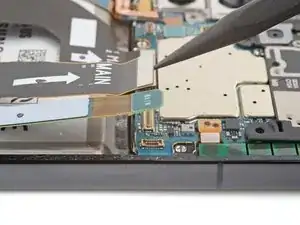
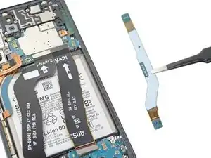
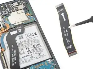
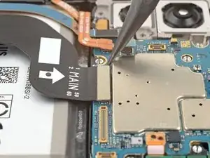
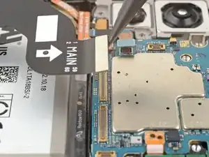
Use the pointed end of your spudger to pry up and disconnect both interconnect cables from the charging board.
-
-
-
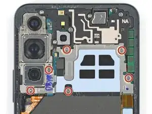
Use your Phillips screwdriver to remove the four 3.5 mm-long screws securing the motherboard cover.
-
-
-
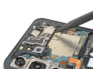
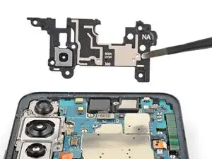
Insert the pointed end of your spudger between the bottom of the motherboard cover and the motherboard.
-
Pry up on the cover to unclip it from the frame.
-
-
-
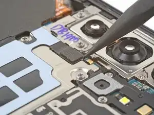
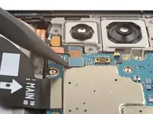
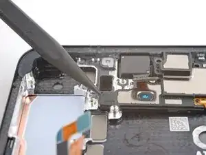
Use the pointed end of your spudger to pry up and disconnect the left 5G mmWave antenna press connector.
-
-
-
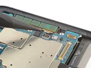
Use the pointed end of your spudger to pry up and disconnect the front-facing camera press connector.
-
-
-
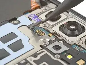
Use the pointed end of your spudger to pry up and disconnect the right 5G mmWave antenna press connector.
-
-
-
Use the pointed end of your spudger to pry up and disconnect the power and volume button's press connector.
-
-
-
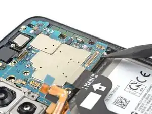
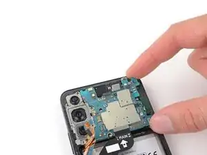
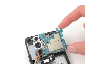
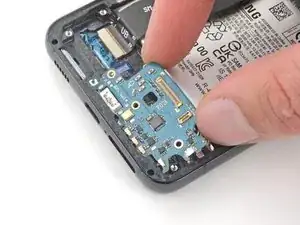
Insert the pointed end of your spudger between the bottom right of the motherboard and the frame.
-
Pry the motherboard up until you can grab it with your fingers.
-
-
-
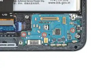
Use your Phillips screwdriver to remove the three 3.5 mm-long screws securing the charging board.
-
-
-
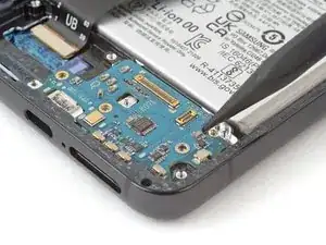
Insert the pointed end of your spudger between the top right of the charging board and the frame.
-
Pry the charging board up from its recess until you can grab it with your fingers.
-
-
-
Grip the charging board by its corners and slide it out of its recess in the frame.
-
Remove the charging board.
-
-
-
Use your Phillips screwdriver to remove the two 2.9 mm-long screws securing the earpiece speaker.
-
-
-
Insert the pointed end of your spudger under the left edge of the earpiece speaker.
-
Pry up to unclip the earpiece speaker from the frame.
-
-
-
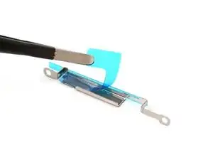
Use your Phillips screwdriver to remove the two 3.5 mm-long screws securing the lower 5G mmWave antenna.
-
-
-
Remove the antenna and connector from the old bracket.
-
Remove the L-shaped adhesive liner from your new bracket.
-
Place the antenna in the bracket's recess with the connector fed underneath the longer screw mount.
-
Remove the thin adhesive liner on the outside of the bracket before installing it in the frame.
-
-
-
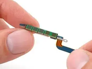
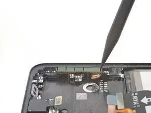
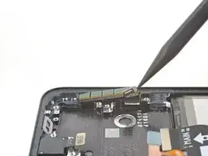
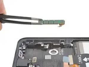
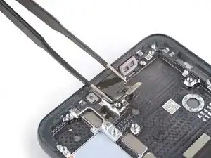
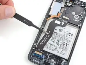
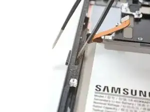
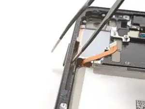
Insert the pointed end of your spudger in the gap between the upper 5G mmWave antenna and the frame
-
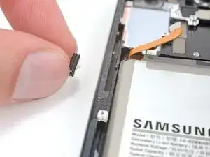
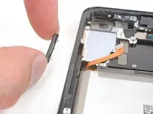
Pry the antenna out of its recess until you can grab it with your fingers or blunt nose tweezers.
-
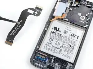
Remove the upper 5G mmWave antenna.
-
-
-
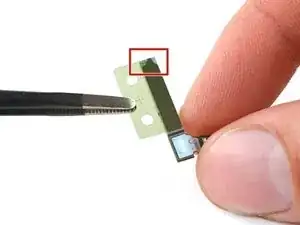
Remove the existing adhesive from the antenna with blunt nose tweezers or your fingers.
-
Remove the clear liner from your new adhesive.
-
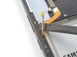
Apply the new adhesive to the bottom of the antenna, with its round end farthest from the connector.
-
Remove the green liner from the adhesive before reinstalling the antenna in the frame.
-
-
-
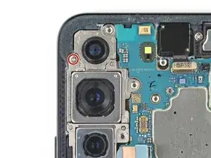
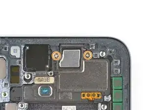
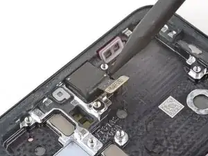
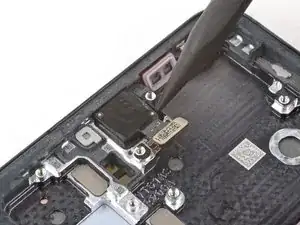
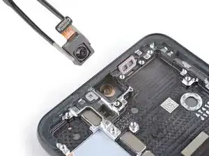
Use a pair of blunt nose tweezers to grab and remove the front-facing camera from its recess.
-
-
-
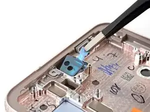
Remove the black adhesive liner from the front-facing camera recess.
-
Peel and remove the foam liner from the new frame.
-
-
-
Remove the clear liner from the front-facing camera adhesive.
-
Place the adhesive in the camera recess with its pull tab facing right.
-
Remove the blue adhesive liner using its pull tab.
-
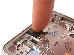
Insert the front-facing camera into its recess in the frame and apply pressure to secure it.
-
-
-
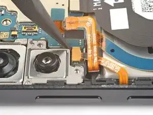
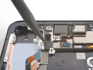
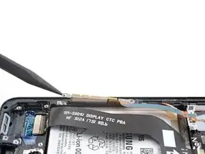
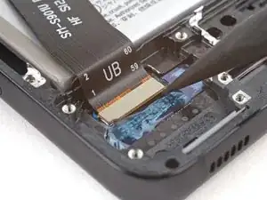
Use the pointed end of your spudger to pry up and disconnect the display cable press connector.
-
-
-
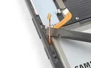
Insert the corner of your spudger in the tab on the power and volume button bracket.
-
Twist the spudger upward to pry and loosen the bracket from its recess in the frame.
-
-
-
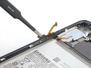
Use blunt nose tweezers or your fingers to grab and remove the power and volume button bracket.
-
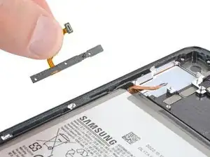
Use your fingers to grab and remove the button pad.
-
-
-
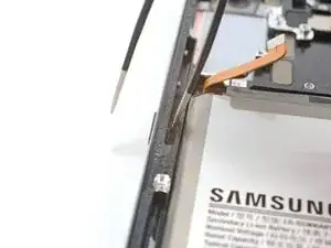
Insert one arm of your blunt nose tweezers into the power button's recess.
-
Press against the power button's peg to separate it from the frame enough so you can grab the button with your fingers.
-
Use your fingers to grab and remove the power button.
-
-
-
Insert one arm of your blunt nose tweezers into the volume button's recess.
-
Press against both of the volume button's pegs to separate them from the frame enough so you can grab the buttons with your fingers.
-
Use your fingers to grab and remove the volume buttons.
-


To reassemble your device, follow these instructions in reverse order.
Take your e-waste to an R2 or e-Stewards certified recycler.
Repair didn’t go as planned? Check out our Answers community for troubleshooting help.

6 comments
In order to best retain the water resistance, how can I best reapply the adhesive? Do I just use the adhesive that was already there or do I need to buy some?
Hi Niall! We wrote a guide describing the process of reapplying adhesive. Click here to see that guide. If your replacement part didn't come with adhesive, then you'll need to buy some, or cut thin, double-sided tape to apply in the same places as the old adhesive. My personal tips, once the new adhesive is in place, is to heat the back cover and firmly press around the edges. Then, lay something heavy on the phone to provide even pressure on the back cover (be careful of the camera bump) overnight. Good luck with the rest of the repair!
After replacing, does the fingerprint reader still work?
Hi! The fingerprint sensor is built into the screen assembly on the S22 models. Your new screen and battery may need to be reset or recalibrated. Here's some basic information regarding the S22 fingerprint reader, which may be a helpful starting place: https://www.samsung.com/uk/support/mobil...
Quick note on the replacement screen. Mine came from you guys with new power/volume buttons and earpiece speaker already installed.
lowrez -