Introduction
-
-
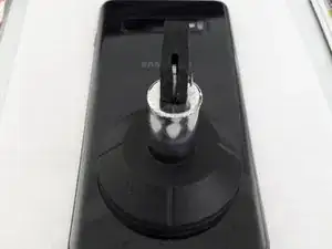
Using a heat gun , heat up the battery cover
-
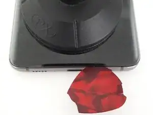
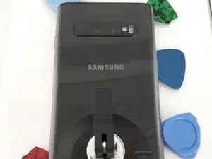
Use a scution cup and a pick to get between the back cover and frame. CAUTION is needed as the back cover is glass and can break fairly easily.
-
As you work the back cover loose, leaves the picks at certain points, so the back cover does not become re-glued to the frame.
-
-
-
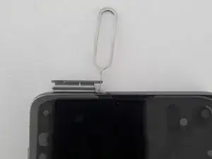
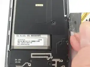
Now remove the screws for the Antenne Panel cover + NFC Wireless Charging on the upper half of the phone.
-
Next remove the screws from the loudspeaker cover on the bottom half of the phone.
-
-
-
Using a thin metal spudger, pry lightly between the cover and frame to release the upper portion of the plastic cover.
-
Cation is needed when inserting the tool between the frame and back cover, as the mainboard is directly beneath the cover.
-
-
-
Using a thin metal spudger pry lightly on the bottom half of the cover.
-
Once it has been loosened, it can be removed as one piece.
-
-
-
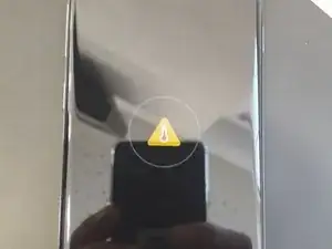
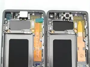
NOTE: After the screen has been replaced, it is advisable to test the display before completely rebuilding the phone.
-
If the antenna and loudspeaker cover are not re-mounted to test the device, then an error will appear when the charging cable is attached.
-
-
-
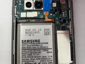
Disconnect the battery from the mainboard, using a plastic tool.
-
Using a heat gun, heat up the front of the display in the area of the battery.
-
Once the glue has been warmed up, use a thin spudger, preferably plastic, to pry the battery loose. It is best to try and pry it up from the frame side.
-
CAUTION: do not pry too hard or use anything sharp to try and remove the battery.
-
-
-
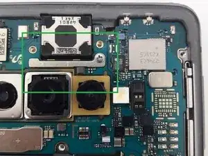
Use a plastic spudger to release the display cable from the mainboard
-
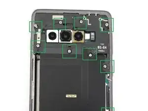
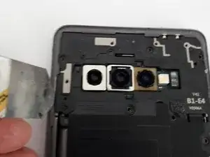
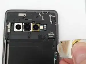
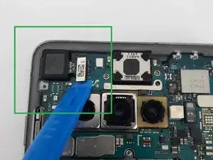
Use a plastic spudger to release the camera from the mainboard.
-
Remove the camera and lay to the side
-
-
-
Remove the retaining screw on the upper half of the mainboard.
-
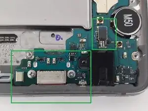
Remove the two screws on the lower half of the mainbaord, either side of the charger port.
-
disconnect the headphone jack connector from the mainboard. The headphone jack can be removed before or after the mainboard.
-
-
-
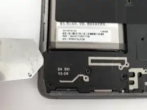
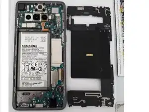
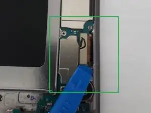
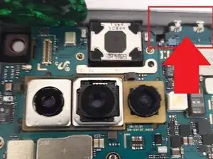
Use a pick or thin plastic spudger to release the mainboard from the top of the frame. CAUTION: there are two metal connectors that can be easily broken or bent, care is needed to make sure they remain intact.
-
Use a spudger to pry the right side of the mainboard up.
-
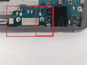
CAUTION: There is also a small metal connector on the bottom that can break easily if bent (Highlighted in the smaller red box). Care is needed when refitting the mainboard.
-
Once the top of the mainboard has been released, you can gently slide the mainboard up to remove the charger port out of the frame. ( Sorry, no picture of this).
-
-
-
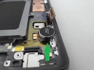
It is possible that the vibration motor & speaker will need to be transferred to the new display. The display that I replaced had the vibration motor and speaker already installed.
-
Once the mainboard has been removed, use a heat gun to heat up the bottom of the vibration motor (from the screen side). Insert a thin, flat edged tool to pry the vibration motor free.
-
Now complete these steps in reverse to re-assemble the device.
-
As mentioned in step 6: To test the device the antenna/loudspeaker cover needs to be attached otherwise an error symbol will appear on the screen.
-


To reassemble your device, follow these instructions in reverse order.