Introduction

A damaged motherboard can cause auxiliary components to malfunction and even prevent it from powering on. If you think your motherboard is causing you problems, follow this guide to replace it on your Samsung Galaxy Note9.

  1. WX1UUEZkqFrkcyVf
    WX1UUEZkqFrkcyVf
    nVDpbDfxJgQnLiNN
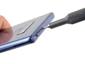
    • Insert a SIM card eject tool straight into the hole in the SIM card tray.

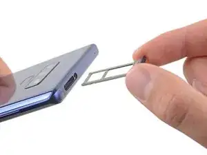
    • Press to eject the SIM card tray.

  2. 3KT6HsUfGSKksx2v
    • Remove the SIM card tray.

    • The SIM card will fall out of the tray easily.

  3. imr3TvrFDDQ2Smgb
    • Power off your phone before beginning disassembly.

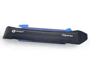
    • Use a hairdryer, a heatgun, or prepare an iOpener and apply it to the right edge of the back of the phone for about a minute to soften the adhesive underneath.

    If using an iOpener it will need to be fully heated and set on for at least 5 minutes. You’ll know the phone is hot enough when its almost too hot to touch.

    Spencer Barron -

    Just came here to say exactly that. The instructions should be amended to state that: "Get it fully hot and leave it there for at least three minutes solid."

    Mister Fixer -

  4. wK5AZqwWYVFHhdpM
    wK5AZqwWYVFHhdpM
    AiS2h1pqRmiTyrnX
    ijSfEkEAirfgkjyB
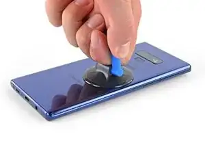
    • Apply a suction handle to the back cover.

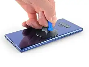
    • Lift with a suction handle to create a gap between the back cover and the frame of the phone.

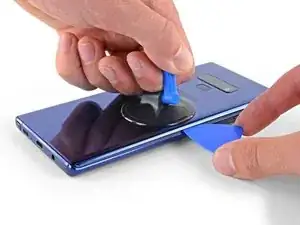
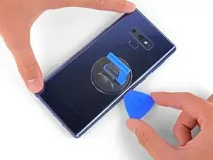
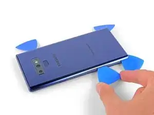
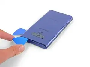
    • Insert an opening pick into the gap.

    • If the glass is badly cracked, cover it in packing tape to create a surface for the suction cup to adhere to.

    • If the adhesive won't budge, apply more heat, not excessive force. Too much force could break the glass.

    It takes so much heat that it is concerning that damage might be caused to the internal parts. It is difficult to heat the glue, pull the case apart and insert the pick at same time. May need some more pointers to handle these situations first, to prevent possible damage. Also what about the glue that is heated and then cooled before opening? Does it run inside and cause greater adhesion after it cools? Another thing, the handling may cause the phone to turn back on while working to separate. Don't know that that is of concern.

    Lou Smith -

    Angle the pick up very slightly so the point goes up into the curve of the glass, not down towards the workings of the phone

    Dean Lee -

  5. phWdatcXskIOnRO3
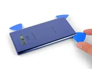
    • Note that there is more adhesive along the top edge and around the camera bezel than around the rest of the phone.

    • Cut carefully around the left edge near the fingerprint sensor or you risk damaging the ribbon cable inside.

    • If, at any point, the adhesive feels stubborn, apply more heat—not more force.

    It's extremely easy to crack the back glass when nearing and rounding the corners. It's probably a good idea to soften the adhesive with heat as you go.

    Aaron Peterson -

    Step 5 is NOT "cut through the adhesive", that's steps 5-10. Step 5 is "Begin the careful process of cutting through the adhesive, starting at the right side where you already softened it. Proceed carefully, slowly, and warmly through the following steps."

    Aaron Peterson -

    These comments are spot-on. I never break a phone, and I cracked the back glass following the instructions without seeing these comments first. Heat the back much more than you think you need and go super, super slow.

    Mister Fixer -

    The bottom inner adhesive layer reaches higher than what you see in the diagram above, so you will have to insert the pick deeper at the bottom and the sides along the bottom to separate the inner adhesive area. Just don't force the corners of the covers upward too much to keep from cracking the glass.

    Drizzt -

  6. YpkbXvVWUIR4Afeb
    YpkbXvVWUIR4Afeb
    FaUbUKoZe6HurIby
    5vZLASPFVpEgMyLC
    • Starting from the center, cut the adhesive up and down the right side with an opening pick.

    • Do not insert the pick more than halfway into the phone when cutting near the fingerprint sensor or cameras, or you risk damaging internal components.

  7. OFSZgLGgXARkwaWJ
    OFSZgLGgXARkwaWJ
    E6TEFVlXsPNDGGHi
    FFeOmLNySIi2VTct
    • Be careful near the corner, as the glass is very weak. Apply more heat at any time if the adhesive becomes stuck.

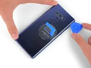
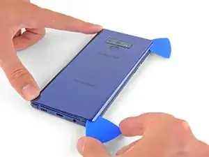
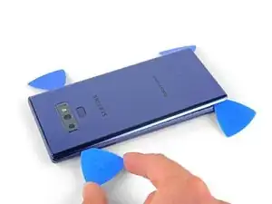
    • Leave an opening pick in the upper-right corner.

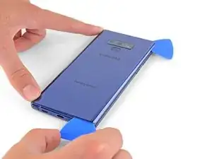
    • Use another opening pick to cut the adhesive around the bottom-right corner.

    • Leave that opening pick in the phone.

    There seems to be a lot of glue at the bottom, I broke the glass as I was cutting past the charging port - not sure if it was already fractured or just not enough heat (I used Sellotape so it didn't break up into pieces!)

    I think LOTS of heat & patience is the key!

    Be very careful around the corners and bottom (probably top too, but I didn't have a problem there). Make sure you've cut in far enough down the side first (go in about 1cm) but less round the corners and work in slowly.

    Dean Lee -

  8. 2jDIRHRfM2FgHNFR
    • Use a heat gun or hair dryer or apply a heated iOpener to the left side of the rear panel for at three minutes to soften the adhesive underneath.

    If using an iOpener it will need to be fully heated and set on for at least 5 minutes. You’ll know the phone is hot enough when its almost too hot to touch.

    Spencer Barron -

  9. 1mtB1lSGkZWyMSrM
    1mtB1lSGkZWyMSrM
    4K246ldIYZVMViQv
    FFMXuXrVm2DpNhZ6
    • Be careful near the corners, as the glass is weakest there.

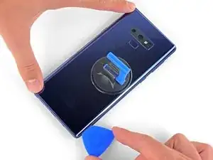
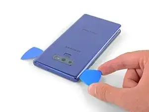
    • Insert an opening pick into the lower-left corner of the rear panel.

    • Using another opening pick, cut the adhesive along the left edge of the rear panel.

    • Don't insert an opening pick in more than halfway on the left edge near the fingerprint sensor or you may damage the ribbon cable inside.

    • It is fine if opening picks fall out as the back cover becomes separated.

    Aside from the left edge where the fingerprint sensor cable is, you may have to insert the pick up to 2cm on the sides and top, and a little further along the bottom, and swipe sideways to separate the inner adhesive areas. If one side doesn't separate fully, just apply heat, insert the pick deeper into the phone, and swipe sideways until the back cover detaches. There isn't a need to apply much vertical force, especially on the corners, since the cover will just pop up once all the adhesive has been sliced by the pick.

    Drizzt -

  10. nNSpwZdhgreWl3rh
    nNSpwZdhgreWl3rh
    DrwI6NpI44hU5bGQ
    6tniPN2RFyvbFgLv
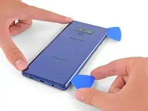
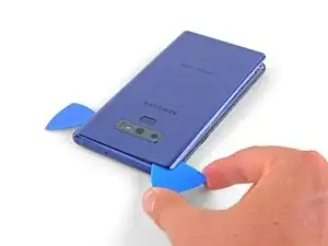
    • Using the inserted opening pick, carefully cut the adhesive around the upper-left corner of the rear panel.

    • Finally, cut the last of the adhesive along the top of the phone.

    • Use an iOpener, hair dryer, or heat gun to apply more heat as needed where you are cutting the adhesive.

    Be VERY patient as you slide the opening picks around the periphery of the glass, and use heat very liberally. Make sure the smooth, clear aspect of the iOpener is against the glass, not the rough black portion.

    David Gitlitz -

  11. CFGPd5CUmuDGj14k
    CFGPd5CUmuDGj14k
    XadxJ3X5cMDYZdsS
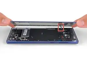
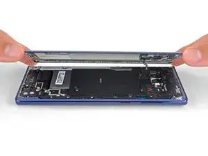
    • Separate the right side of the rear cover first.

    • Tilt the cover up along the left edge to expose the fingerprint sensor ribbon cable.

    • Do not pull out the fingerprint sensor ribbon cable yet.

    • The fingerprint sensor cover might stay attached to the midframe.

    Thought I'd done something wrong here as there wasn't a cable attached to the back - the fingerprint reader hadn't come away with the back, but had stayed with the phone.

    Dean Lee -

    Exactly the same experience. Made life a little easier.

    Mister Fixer -

    Happened to me as well.

    David Gitlitz -

  12. EOB5BnuPwLiWhRJy
    EOB5BnuPwLiWhRJy
    pvUG6RHyuIevnBsT
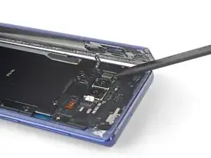
    • Use the tip of a spudger to pry the fingerprint sensor ribbon cable up and out of its socket.

    On my phone the fingerprint sensor did not come off with the back cover but stayed on the phone!

    Dean Lee -

  13. fxtTpIwKVs1XBASZ
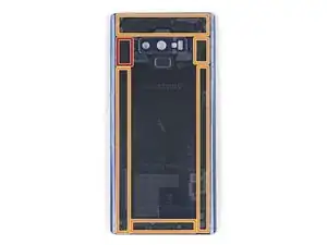
    • Remove the back cover.

    • To re-install the back cover:

    • Use tweezers to peel away any remaining adhesive from the phone's chassis. Then clean the adhesion areas with high concentration isopropyl alcohol (at least 90%) and a lint-free cloth to prep the surface for the new adhesive. You don't have to clear out adhesive down to the plastic but larger pieces should be removed.

    • Turn on your phone and test your repair before installing new adhesive and resealing the phone.

    • Carefully apply the new adhesive to the back cover, then line up one edge of the glass against the phone chassis and firmly press the glass into the phone.

    I am installing a new backplate (this is my first repair; I was CERTAIN that I would crack the back glass, and I was NOT wrong) but I’m not sure how tweezers are meant to remove gooey adhesive! I simply used the blue plastic pry tool as a scraper and gently rolled up the goo. Maybe the glue is different because I have a refurbished phone? That may also explain why I had so much trouble with Step 1. Hope that this helps!

    Christopher Yarlott -

    Use tweezers remove any inner adhesive strips that may have started peeling off when the back cover is removed, or adhesive clumps. If an adhesive starts to peel off, use tweezers to pull the strip off completely, and then replace only that removed adhesive strip. Actually, the iFixIt inner adhesive strips don't seem to have the white non-stick areas that are on the original adhesive strips. Thus, it seems ok to keep the original inner adhesive strips if still attached to the phone.

    The outer adhesive border is like a good, not a strip, and should be replaced. Using isopropyl alcohol to rub off only the edge adhesive on the phone and back cover works well.

    After adding a new outer adhesive and reattaching the back cover, you have one try to align and replace the cover. The cover might not attach flush onto the phone with no side gaps, due to the outer adhesive strip placement. It is probably sufficient if the outer adhesive seals all the way around the back cover border.

    Drizzt -

    While testing the phone after battery replacement, but before reattaching the back cover, if a thermal warning (triangular thermometer icon) appears during charging that prevents charging over 50%, remove the charging cable and use a lightly warmed iOpener or heat gun on the battery to warm it slightly. Once the battery is warmed up a little, reattach the charging cable, and the error should go away. Battery charging can be resumed. This assumes no hardware was damaged during battery replacement.

    Drizzt -

  14. NpvMRUlwISOMrGih
    NpvMRUlwISOMrGih
    xEFdupFYZIyOQham
    • Use a Phillips screwdriver to remove the nine 4 mm screws securing the upper midframe.

    There are two more screws on the bottom right corner of the little side frame that the Qi plate is glued to. I took those out as it put less stress on it.

    John Stone -

    It helps to hold the fine tweezers with your non-dominant hand to support the screw heads and ensure they come straight out; you can also gently lift as you unscrew.

    David Gitlitz -

  15. TtRQbpjOgwgKyCeU
    TtRQbpjOgwgKyCeU
    qnfyfoRPVUgOHdxi
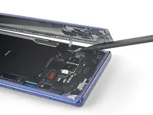
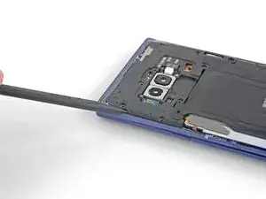
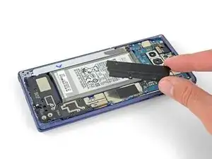
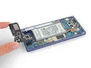
    • Insert the tip of a spudger into the upper-left corner of the upper midframe.

    • Pry the upper midframe out of the phone.

    • The upper midframe snaps into and out of place.

  16. WPl3OTEYUWaQk4lw
    WPl3OTEYUWaQk4lw
    OtIWY55KKKuAKdUL
    pRScXCbeMtNfmfgF
    • Peel the wireless charging coil off the battery starting with the left side.

    • The adhesive is weak but you can use an opening pick to cut it if necessary.

    • During reassembly start by snapping the midframe into place first before adhering the wireless charging coil.

    Be careful not to tear it as it comes off - especially the side bits that stick out a bit

    Dean Lee -

    You can actually leave the right side of the coil attached to the phone so that it is easier to align and reattach afterward.

    Drizzt -

  17. MDPfHEnbaBBwN5DS
    MDPfHEnbaBBwN5DS
    3SnhFaqu3LXtjZNv
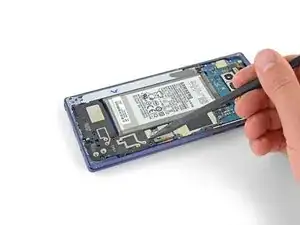
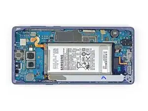
    • Use the tip of a spudger to disconnect the orange ribbon cable connecting the battery to the motherboard.

  18. GIEOQCkaq2ssMnNP
    GIEOQCkaq2ssMnNP
    b3B3LhmeIptyAZTV
    • Remove the nine 4 mm Phillips screws from the plastic cover next to the battery.

  19. VXVo3wSUB3IJUWEu
    • Remove the plastic cover next to the battery.

  20. 5QlYhKgVE5OP2ukX
    5QlYhKgVE5OP2ukX
    huJEMLiBUEjobIgG
    CfJJURuidtGIxGKW
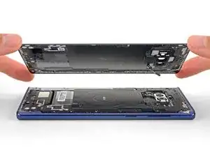
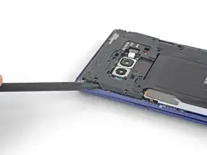
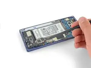
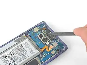
    • Insert the tip of a spudger into the top of the lower midframe.

    • Pry the lower midframe out from the phone.

    • The lower midframe snaps into and out of place.

    • Remove the lower midframe.

  21. YmgeJOmh32rWGZQP
    YmgeJOmh32rWGZQP
    mYUOnVXlM1OmlsVI
    W6RTphFsIxwXrNwo
    • Use the tip of a spudger to pry the front camera connector straight up and out of its socket.

    • Use tweezers to remove the front camera.

  22. gGXaKTjBwqXqIrDu
    gGXaKTjBwqXqIrDu
    KEeHA6iBqKgaGRBj
    STApeHUtwk1Wi5MA
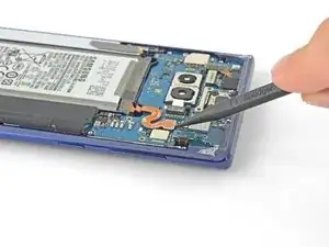
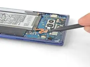
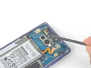
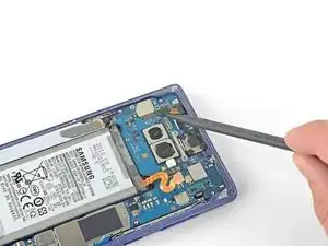
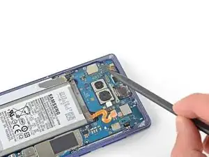
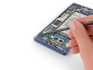
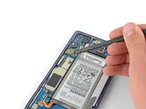
    • Use the tip of a spudger to disconnect the iris scanner from the motherboard.

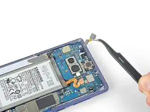
    • Use tweezers to remove the iris scanner.

  23. TEPfQM2pUKxMZjyn
    TEPfQM2pUKxMZjyn
    T5AygZIO1dKbF6M1
    • Use the flat end of a spudger to pry the front sensor connector out of its socket.

  24. JAVgH6GKVcktGsDN
    JAVgH6GKVcktGsDN
    OS2sMRIBaMCRRyRG
    • Use the flat end of a spudger to disconnect the display cable from the motherboard.

  25. FqksMRN1WMWmOFm4
    FqksMRN1WMWmOFm4
    CKLiCNWNS6pvFTFd
    • Use the flat end of a spudger to disconnect the touchscreen cable from the motherboard.

  26. lmjRQDFPIXsREwxx
    lmjRQDFPIXsREwxx
    UJ44fKWmaKhNP4li
    • Use the flat end of a spudger to disconnect the charging assembly from the motherboard.

    These screws are supposed to be 3.2 mm because when I took out these screws, they were shorter than the ones you take out first

    Lizmaris Morales -

  27. XjeGwpUWiAsFYFjN
    XjeGwpUWiAsFYFjN
    SsewRVXKSa21JpQD
    • Remove the three 4 mm Phillips screws securing the motherboard.

    • There are triangles next to the holes indicating the motherboard screw locations.

  28. UJRbDi4PVRDEQsMa
    UJRbDi4PVRDEQsMa
    4uQmkLjXVjrjcDJH
    4fZwgYRoBKBgTgIY
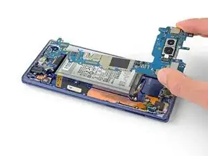
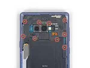
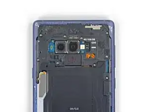
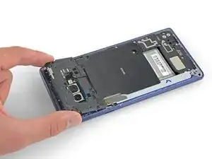
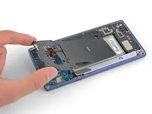
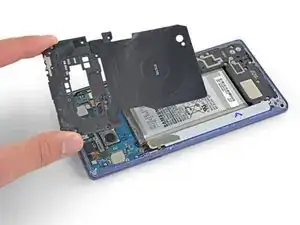
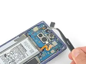
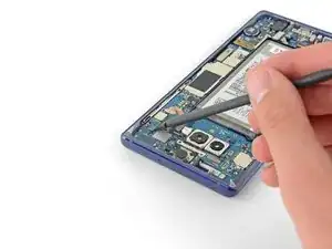
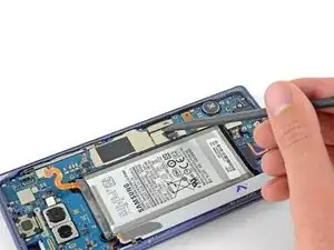
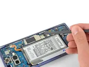
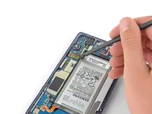
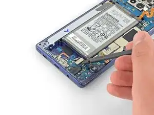
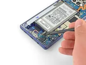
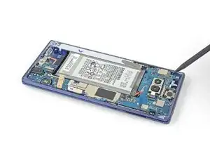
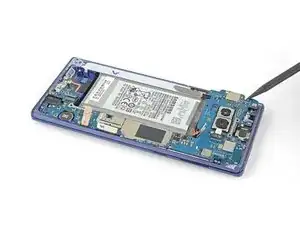
    • Use a spudger to gently lift the motherbord from the upper-left corner.

    • Carefully remove the motherboard.

    • Move the ribbon cables out of the way as necessary. Do not pull the motherboard out if it becomes snagged on any cables.

Conclusion

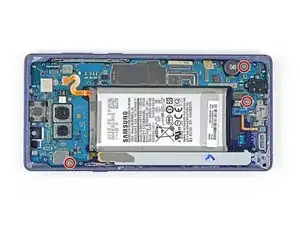
To reassemble your device, follow the above steps in reverse order.

Take your e-waste to an R2 or e-Stewards certified recycler.

Repair didn’t go as planned? Check out our Answers community for troubleshooting help.

Compare your new replacement part to the original part—you may need to transfer remaining components or remove adhesive backings from the new part before installing.

Sam Omiotek

Member since: 25/02/19

81109 Reputation

6 comments

Thats a really great instruction. I also have a question. Can I replace the internal memory in a new Note 9 phone from an old Note 9 Phone? If yes, will it work and does it have to be same storage size?

Thank you

talhamahmud zim -

Thank you! Unfortunately this is not possible because the memory is soldered to the motherboard. What you can do is swap the entire motherboard from an old phone into the new one but I haven’t tested this myself so I can’t guarantee that everything will work properly. I expect it to work though—including for larger storage sizes—because I do not know of any parts that are paired to the motherboard on those phones.

Sam Omiotek -

Hi, can i replace a dual sim Note 9 with a single sim Motherboard?

soler.debbiemay -

Hello can i put a motherboard from an international model into an us frame?

khoi cao -

Hi

I need to find the CPU and hard direction for resold and reball the those ic

Wizardzx -

I can't use the wifi

The phone turn off after i activate it

Do you have any idea to fix the problem?

khefifi mohamed -