Introduction

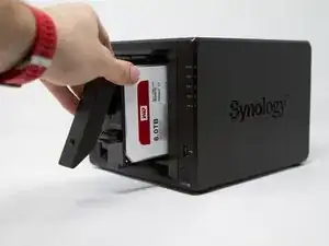
Here's a step-by-step tutorial to dismount each piece of the NAS until you reach the motherboard.

'Note: the interest of this tutorial is however limited.'

Indeed, most of the components that a user can be brought to add or change are now accessible directly, without disassembly (storage disks, memory expansion, SSD cache).

This is a step forward since, for example, a DS415 + / DS916 + must be completely removed to change a single RAM array.

Only the memory stack on the motherboard and fans remain inaccessible directly and require the disassembly of the NAS described in this tutorial to be changed (whether they are HS or replace them not the best).

The dismantling time is estimated at one hour (a single experiment on the timer). That said, it is certainly achievable in 20/30 minutes.

The photographs were taken with a CANON EOS 7D and an iPhone SE, using a portable LED studio.

  1. XBxx2gnjXxXBJyEc
    XBxx2gnjXxXBJyEc
    hmbnUxP2vesSE5Xk
    2nLGkEsj3gIvMbu5
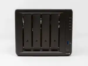
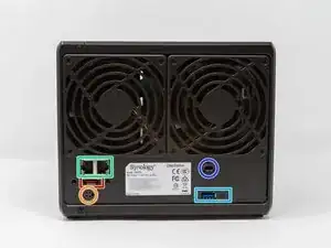
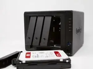
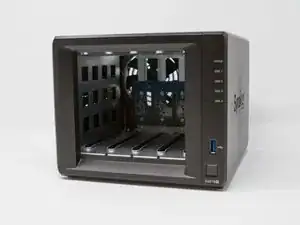
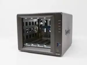
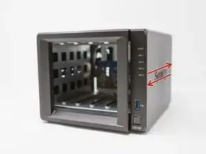
    • Here are the different interesting faces of the case: front (bay disks), rear (connectors and fans), below (2 hatches SSD).

    • This NAS DS918 + is equipped with 4 GB of RAM (8 GB max.), An INTEL Celeron J3455 64-bit Quad processor, four bays for SATA drives.

    • 2 RJ45 Gb ports.

    • Kensington security incision (K-lock)

    • 2 M.2 NVMe 2280 ports (disk cache)

    • 1 port for power supply

    • 2 USB 3 ports (1 in front and 1 behind)

    • 1 eSATA port

  2. AGhaFAY4ciEHA3Ri
    AGhaFAY4ciEHA3Ri
    gJfIprEjnVrUDRpa
    • Before teardown, unlock the disk media with the key.

  3. CmdNLiRB1RVj3RVr
    CmdNLiRB1RVj3RVr
    11n6DZy5m4P5Dfsi
    HOOauiPqYcDyb2Ce
    • Since the media are unlocked, remove each disk media.

    Please remember for Active installations to label and replace your disks in the exact same order.

    James Needham -

  4. tBuJGJmySVATiwdi
    tBuJGJmySVATiwdi
    hPik2lso3riVEjDs
    IkrTJEaW1iQ3jOlN
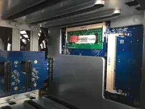
    • This is a significant innovation, the memory is now directly accessible and without disassembly of the housing, for the original bar as for the extension port.

  5. LqjAbJOQ2BdaXGjE
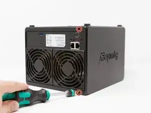
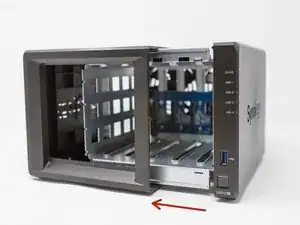
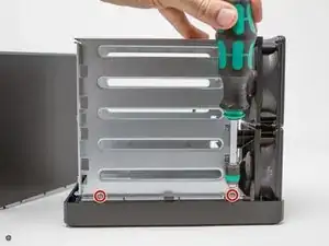
    • Remove the 2 screws on the back of the case at the top and bottom (not the one above the USB port)

  6. BrlAVdt65ZFL6LgK
    BrlAVdt65ZFL6LgK
    KqYpTApSWFGZKkyS
    ViRf61ZcEN1A4S6j
    • Slide the cover forward, then slide it out (here, to the left).

    Any mounted SSD needs to be removed first, as otherwise the housing can get stuck on those and cause the SSD lock to disengage or even damage the SSD.

    Aemony -

  7. PNyEkfT5VLdmZVlF
    PNyEkfT5VLdmZVlF
    ZTsAtlbHtgwSmhAX
    3FrmeHHhFDQZLQbr
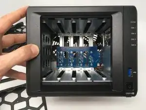
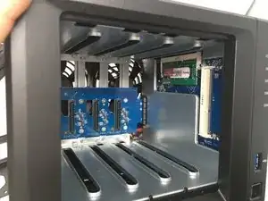
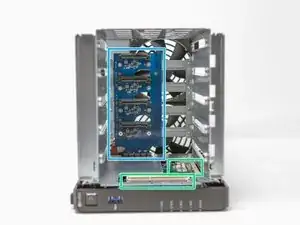
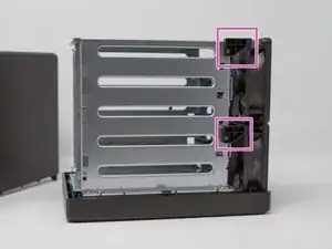
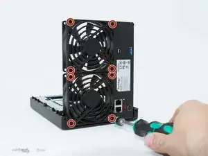
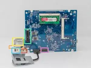
    • in red: SSD M.2 expansion card 2280

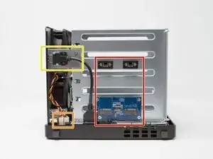
    • in yellow: USB port 3

    • in orange: internal connectors of the 2 fans

    • in green: 2 slots of RAM

    • in blue: SATA III backplane (4 hard drive bays)

    • in pink: fixing the fans on the chassis

    I want to replace just the backplane. Step 13 appears to show this coming out with the cage. But, is it possible to remove/replace the backplane without removing the cage & M.2 expansion card ?

    Robert Shalford -

  8. MJKYFvYTIHeMKZDi
    MJKYFvYTIHeMKZDi
    pdPXU2cn5R4qXvEW
    qbjrgOYifU5QLZSg
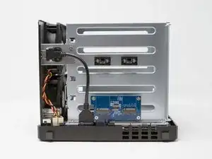
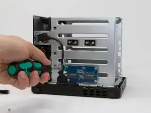
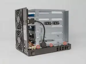
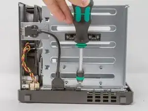
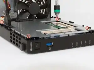
    •   Remove the 4 screws located on the blue electronic board.  

    • You can remove the M.2 expansion board now.

  9. XUSL6ULMmJBjxZQH
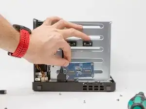
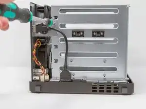
    • Remove the screw from the holding plate of the USB connector 3.

    • Also remove the USB 3 connector screw on the rear side (this can be done later).

    • Do not remove the USB connector 3 on the motherboard, it is glued. It does not interfere with disassembly!

  10. BSykmOqXAV5t2ptK
    • Remove the screws from the two shims to secure the disc cage and the two fans.

  11. gMcoU4lbmuEWDySQ
    gMcoU4lbmuEWDySQ
    NmAVSsQ2U6Qsb66j
    • 5 Phillips screws must be removed.

    • First 3 screws on SSD expansion board, on the bottom (bottom).

  12. kXTEaXYvAF6sFSvH
    • Then 2 screws on the upper face of the device (top).

  13. loMAHBAgDaeYuJDD
    loMAHBAgDaeYuJDD
    iTZlNAZHU6mjitas
    kl4mvZ2AtSNvWflK
    • Now that the screws have been removed, you can (after verification) remove the cage drives.

    • Attention to the backplane and its connector (the electronic card). Check and check again, without forcing! The cradle discs must come alone.

  14. 44YG6mCtAWrO6iKi
    44YG6mCtAWrO6iKi
    shHq4SHuWHeNQrWd
    ttIptLUATtMP3la6
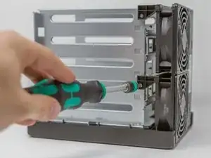
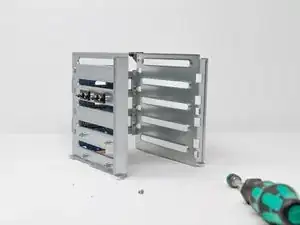
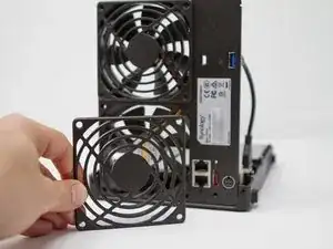
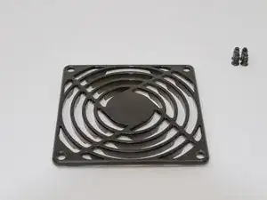
    • Remove the 8 screws from the fan grilles. They make it possible to maintain both the grilles and the fans.

    • Removing the fans does not seem necessary (not taken the time to check) to remove the motherboard.

    • Attention, when it comes to reassemble the grids, it will be necessary to make sure to align the 2 very small lugs in relief on the back of the plastic grates with the 2 small holes between the screws of the bottom of the fans!

    Confirmed: the motherboard can be removed with the fans still attached (eg. for access to the reset switch if it is faulty)

    Mike Wyer -

  15. 6EFpHCZxSTDf2d5b
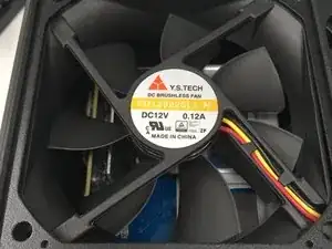
    • According to the technical documentation of Y.S. TECH:

    • Voltage: 12 Vdc (7 to 13.2 range) for 100 mA (consumption)

    • Life time @ 40 ° C L10: 50000 h

    • Noise level: 23 dB

    • Max airflow: 36.3 cubic feet / minute

    • Rotation speed: 1900 rpm

    • Weight: 100 g

  16. 34WoJek3XHvFAnZQ
    34WoJek3XHvFAnZQ
    TemAWt2ZxipoYLiW
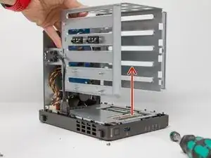
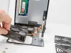
    • Remove the power cables from the fans, being careful to locate them (you never know) located on the motherboard.

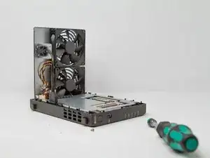
    • Then remove the fans.

    • You will also be careful to unscrew the USB 3 connector fixing screw on the rear panel (if this has not been done previously).

  17. NiDxGl1DGMN2m6NN
    NiDxGl1DGMN2m6NN
    6EeMvyrOMrBfvTwX
    qK4gByaQ246KXxQl
    • Remove the 4 screws that secure the motherboard to the case.

    • Remove the motherboard from the case paying attention to the USB 3 connector on the front and the power button. To do this, move the front panel a little and lift the motherboard upwards (outside).

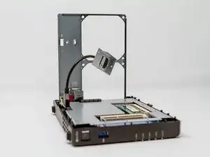
    • Once the motherboard is out, unscrew the 4 screws of the metal protective cover (metal plate).

  18. slcIFxRo5sVFXykA
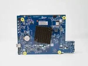
    • Motherboard processor face

    • INTEL Celeron J3455 / 64-bit / Quad core 1.5 burst up to 2.3 GHz

    • Memory battery

    • Internal Beep

    • USB connector 3

    • Power button (power-on)

    • Flash memory with pre-loaded DSM 6.1 kernel to allow the NAS to boot before full installation of the OS

    • UEFI Insyde H2O BY56 chip ??

    The reset switch is the small white component under the ethernet ports (on the far right of this photo).

    It snaps off easily with a pair of pliers.

    Mike Wyer -

  19. lGhQcg2LvwkGJsJD
    lGhQcg2LvwkGJsJD
    YcYu4BKsACoPpFUX
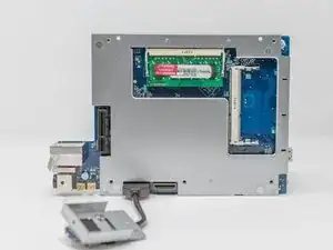
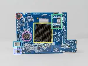
    • Memory side of the motherboard (pre-equipped with 4 GB of RAM)

    • NVMe M.2 SSD expansion card connector

    • Connector (PCIe ??) for SATA disk expansion card

    • Fan connector (x2)

    • Power connector

    • RJ45 LAN Connector (8P8C) x2

    • ESATA connector

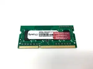
    • Original 4GB DDR3L RAM Memory Stick 1866

    Can someone add a functional HDMI directly on the motherboard?

    joe nyaga -

Conclusion

To reassemble your device, follow the instructions in reverse order.

Be careful however, for the grilles of the fans it will be necessary to make sure to align the 2 small raised lugs on the back of the plastic grilles with the 2 small holes between the screws of the bottom of the fans!

Sébastien

Member since: 14/12/15

4136 Reputation

15 comments

Un tutoriel complet, avec de bonnes photos, lecture claire et concise.

Bravo et merci pour ton travail.

Jordi Chavarria -

merci pour ces encouragements !

Sébastien -

Hi

Is the cpu upgradable or soldered directly to the bord ?

Thanks

safeburn -

Hi,

soldered. But i haven’t removed the thermal dissipator.

Sébastien -

can you try it to upgrade it? :)

peto01 -

I’m very curious to what the unsoldered (blank) header (J3) on the back of the mainboard is.

Brian de Jong -

Are the fan connectors just regular 3-pin connectors found on 92mm Noctua fans?

Daniel -

Yes.

The best choice is the NF-A9 FLX with only 17,1dB/A…

https://noctua.at/fr/products/fan

I’ve installed this fan on my DS918+ and I can confirm it works just fine.

Emmanuel -

But… be aware that the design of the 4 arms that support the ball bearing is not the same on the Noctua than on the original YST fan. They are turning in the opposite direction…

https://www.techpowerup.com/reviews/Syno...

https://images-na.ssl-images-amazon.com/...

Problem: the DS918+ fan grills are not flat, they are partly in relief and this relief is designed to fit exactly in between the YST fan ball bearing arms… (look at the bottom of the grill)

https://d3nevzfk7ii3be.cloudfront.net/ig...

So once the Noctua fan installed, the Synology grills won’t fit properly any more.

You’ll either need to buy flat grills to use them instead of the original ones.

Or use washers to keep the original grills angles flat.

Or screw without washers but it will push the angles down while the center will be stuck by the relief and it will then round the grills.

Emmanuel -

Well spotted, thank you!

I'll thus replace the stock grills by these: https://amzn.eu/d/fZIURx0

Dimitri Hautot -

Merci beaucoup pour ce tuto très bien fait

Alex Mc -

Merci Alex !

Sébastien -

Merci beaucoup pour ce tutoriel. C’est toujours intéressant de voir ce qui se cache dans nos appareils.

Manuel -

;) c’est un plaisir !

Sébastien -

Ganz tolle, informative und super bebilderte Anleitung. Auch wenn ich noch die DS418 habe, hat mir diese Anleitung sehr geholfen.

Dank an den Ersteller !!!

Martin -