Introduction
The Pure Evoke F3 radio marketed about 2017 and bought Aug 2020 had started to operate erratically and failed to work at all in Nov 2024, showing just the illuminated 'PURE' logo. It had not had excessive use, but was continuously on standby.
Extracting the 3 circuit boards showed that 2 of the 30 or so electrolytic capacitors showed slight leakage at the base (and high ESR readings). These were replaced and the radio was fully functional again.
Tools
Parts
-
-
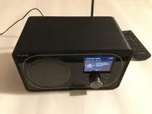
The image shows the general view of of the DAB/FM/internet radio in the working condition after the repair. Before the repair, the display showed only the 'PURE' logo and none of the buttons on the front face, or the remote control, worked.
-
-
-
Undo the 6 identical screws on the back and carefully pull the back away from the casing, exposing cables.
-
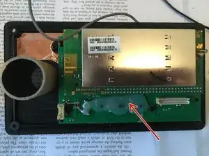
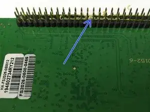
Pull off the two ribbon cables from the rear boards and the other wire from the front board. (Just easier that way). The double layered rear boards should look like the image. Note the hot wax glue (red arrow) which will need removing later.
-
(The front printed circuit board was examined to be OK, so not considered in this repair guide)
-
-
-
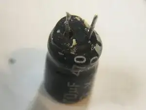
Inspection showed that two of the capacitors had slight leakage from the base. One also had a slight leakage at the top (hand lens needed) and the other had a very slight bulge at the top. The 1st image shows one of the capacitors in situ and 2nd image shows this removed capacitor. Both capacitors were Ketucon 470uF, 10V, -40degC to 105Deg C.
-
For those interested in fault diagnosis: the faulty capacitors had a measured in-situ equivalent series resistance (ESR) of 2.4 and 6.7 ohms ie way in excess of the satisfactory 0.15 ohms. The capacitances were also low at 192uF and 260uF. By measuring ESR, it was easy to spot the faulty capacitors (visual inspection is not quite so obvious)
-
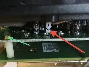
To remove the capacitors, the twin boards, partially held apart by 2 white plastic spacers, must be separated. To do this squeeze the tops of the spacers (green arrow) and lever the boards apart carefully. The boards are also connected by a rigid multi-pin connector. The spacers and connectors may be glued (blue arrow), so ease out bit by bit.
-
-
-
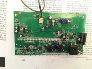
The locations of the two faulty capacitors are shown in the image where I have marked the tops with blue ink.
-
Note in order to change the capacitor nearest the output jacks, it was necessary to remove the hot wax glue (shown in step one) to gain access to the solder. The glue can be levered away with a small jewellers screwdriver or similar after applying a little rubbing alcohol or similar.
-
Note also the capacitors are secured with lead free solder, so the temperature of the iron needs to be a bit hotter than would be used for leaded eutectic Pb/Sn solder. So particularly check that the iron is clean, tinned and well heated up (my cheap unregulated 30W iron worked fine but my small 15W didn't)
-
Note also that the 470uF capacitors are very common and can be reused from most scrap circuit boards if available. They should be 470uF and 10V or above, though if the voltage is higher, the capacitor is physically larger and may not fit when it comes to reassembly as space is a bit tight.
-
-
-
Comment: Ketucon is not known as a bad capacitor manufacturer on the internet, but there are many fakes about apparently. I recall that all the other electrolytic capacitors, both bigger and smaller, were labelled Ketucon and were satisfactory (visually and low ESR).
-
Replacing two faulty leaking electrolytic capacitors on one of the printed circuit boards, got the internet radio working again. The numerous other capacitors in the radio looked OK and were not changed. It's unusual for capacitors to fail after just 4 years use.