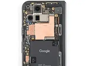
Introduction
-
-
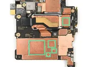
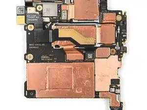
Apply small beads of thermal paste (five total) to the motherboard in the same locations as the old thermal paste.
-
-
-
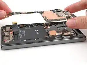
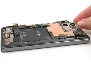
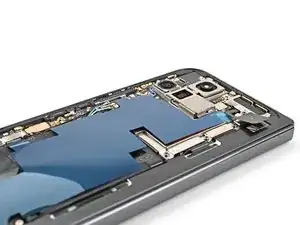
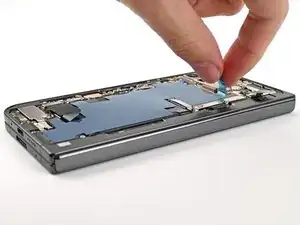
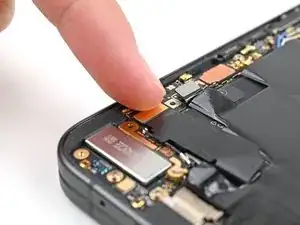
Place the logic board back into its cutout in the frame, making sure no cables get trapped underneath it.
-
-
-
Use a Torx Plus 3IP driver to install the three screws securing the logic board:
-
One 2.2 mm‑long screw
-
Two 2.6 mm‑long screws
-
-
-
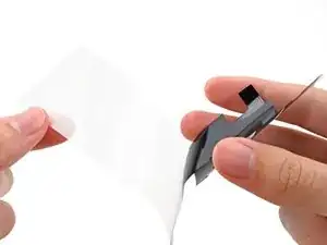
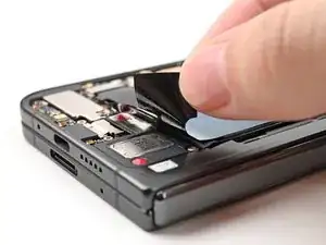
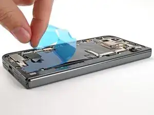
Peel the clear liner off your replacement graphite sheet to expose the adhesive on the upper half.
-
Align the upper half of the graphite sheet over the logic board and lay it down.
-
-
-
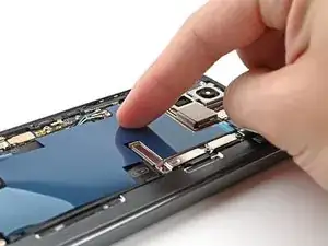
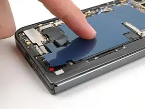
Use your finger to press down the upper half of the graphite sheet and secure it to the logic board.
-
-
-
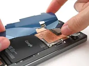
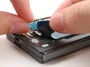
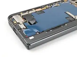
Remove the blue liner from the bottom of the graphite sheet to expose the adhesive underneath.
-
-
-
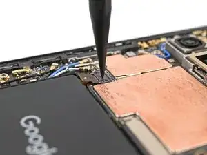
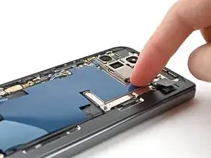
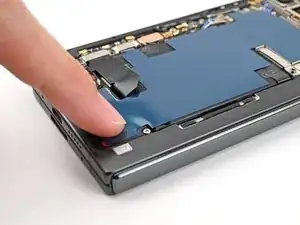
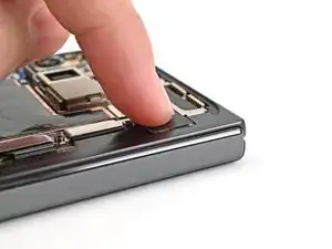
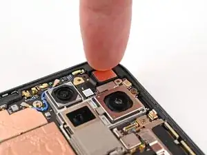
Drag your finger from the middle section of the graphite sheet to the adhesive spot on the loudspeaker to flatten the graphite sheet and adhere it.
-
-
-
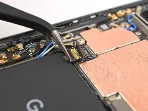
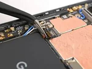
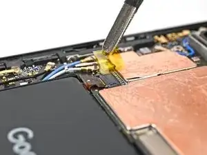
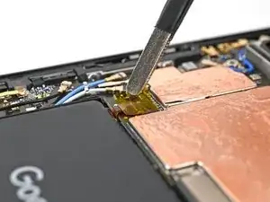
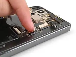
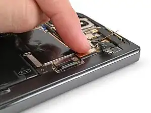
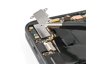
Reconnect the inner display cable and the top and bottom interconnect cable press connectors.
-
-
-
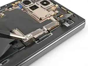
Reinsert the inner display cable bracket clip under its slot in the logic board and align the screw holes.
-
-
-
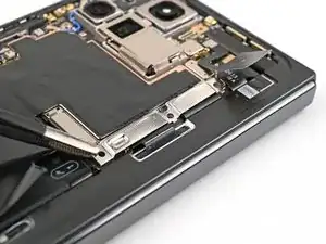
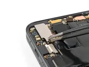
Use a Torx Plus 3IP driver to install the 3.0 mm‑long screw securing the inner display cable bracket.
-
-
-
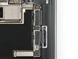
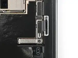
Reinsert the bottom interconnect bracket clip under its slot in the frame and align the screw hole.
-
-
-
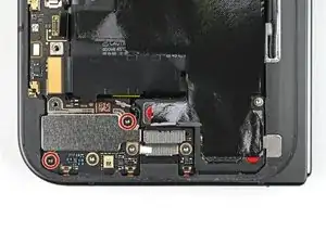
Use a Torx Plus 3IP driver to install the 3.0 mm‑long screw securing the interconnect cable bracket.
-
-
-
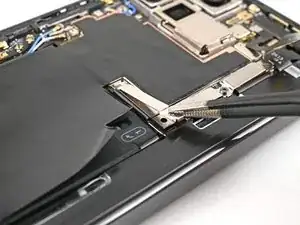
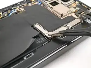
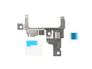
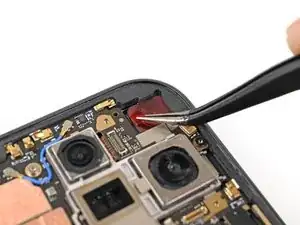
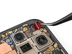
While holding the ultra wideband antenna out of the way, reinsert the ultra wideband bracket clip under its slot in the frame and align the screw holes.
-
-
-
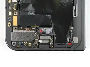
Use a Torx Plus 3IP driver to install the two 3.0 mm‑long screws securing the ultra wideband bracket.
-
-
-
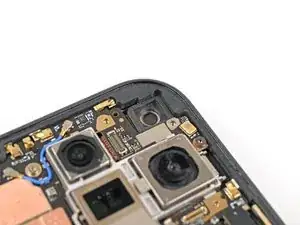
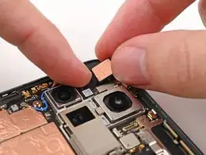
Remove the old adhesive and foam on the ultra wideband bracket and under the antenna.
-
Replace the corresponding adhesive and foam to the bracket and the frame.
-
Press the ultra wideband antenna to the frame and re‑adhere it.
-
-
-
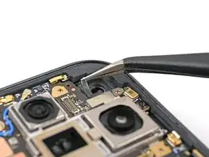
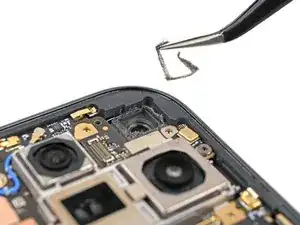
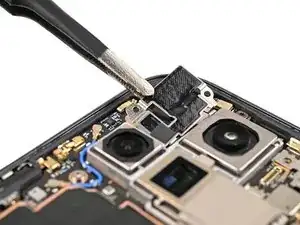
Use tweezers, or your fingers, to remove the old adhesive foam from the inner front camera cutout.
-
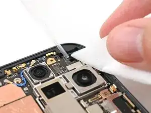
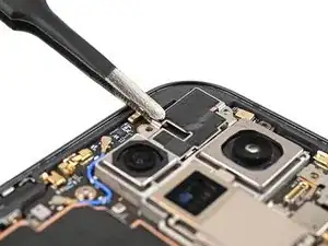
Use isopropyl alcohol (>90% or greater) and a coffee filter or lint‑free cloth to remove any adhesive residue.
-
-
-
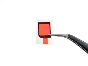
Peel the replacement inner front camera adhesive foam off its clear liner to expose the adhesive underneath.
-
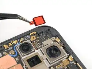
Align the adhesive foam over the cutout in the frame so that the pull tab is facing the bottom of the phone.
-
Place the adhesive in the cutout.
-
-
-
Use the tip of a spudger to press along the edges of the adhesive foam to secure it to the frame.
-
-
-
Use tweezers, or your fingers, to peel off the colored liner and expose the adhesive underneath.
-
-
-
While holding the inner front camera above its cutout, reconnect its press connector.
-
Lay the inner front camera in its cutout and press down to secure it to the adhesive.
-
-
-
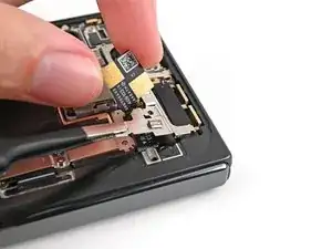
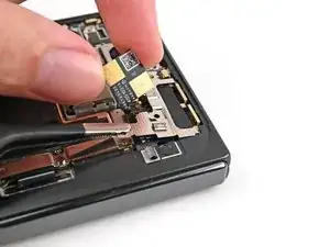
Reinsert the inner front camera bracket clip under its slot in the logic board and align the screw holes.
-
-
-
Use a Torx Plus 3IP driver to install the two 2.6 mm‑long screws securing the inner front camera bracket.
-
-
-
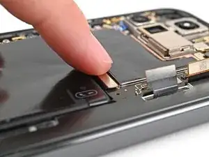
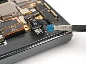
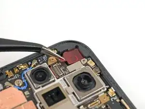
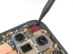
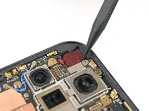
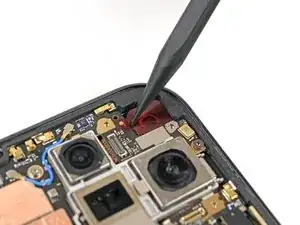
Use tweezers to hold the antenna cable's connector in place over its socket and gently press down with your finger or a spudger until the connector snaps into place.
-
-
-
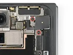
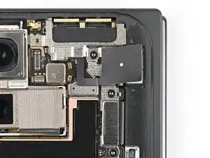
Use a Torx Plus 3IP driver to install the two 3.0 mm‑long screws securing the vibrator bracket.
-


To reassemble your device, follow these instructions in reverse order.