Introduction
If the X-axis bearings in your PRUSA i3 MK3 are worn and need to be replaced they might make noise and prevent the extruder assembly from moving smoothly. If you need to replace the X-axis bearings in your PRUSA i3 MK3, follow the steps in this guide. Ensure that you do not lose any of the parts or socket head screws that are removed during replacement.
-
-
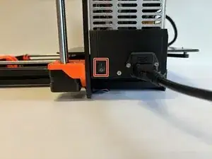
Orient the printer so that the screen is facing to the left.
-
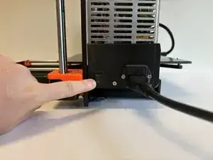
Using the On/Off button, switch the printer into the Off position.
-
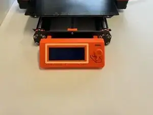
Ensure your printer is off by visually inspecting the screen. If the screen is not lit up, your printer is off.
-
-
-
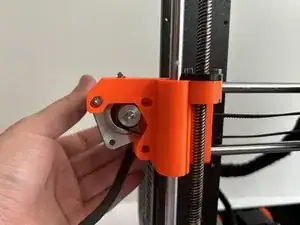
Orient the printer so that the screen is facing away from you.
-
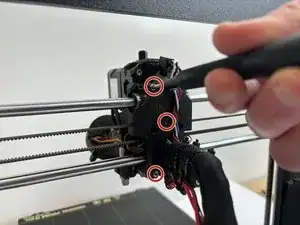
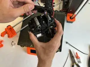
Remove the five 2.5mm X 10mm socket head screws on the back of the extruder assembly.
-
Remove the back cover and pull it away from the extruder assembly. Do not put too much tension on the wires.
-
-
-
Orient the printer so that the screen is facing you.
-
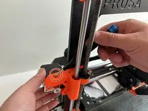
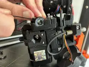
Loosen the 2.5mm X 18mm tension set screw.
-
Loosen the two 2.5mm X 18mm socket head screws on the right, holding on to the X-axis motor.
-
Slightly loosen the 2.5mm X 18mm pivot screw on the left. This screw will act as a pivot for the X-axis motor.
-
Pivot the motor to release the tension on the belt.
-
-
-
Orient the printer so that the screen is facing away from you.
-
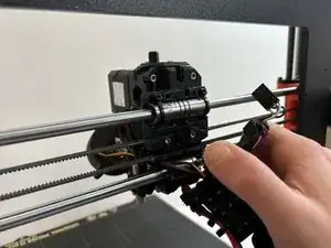
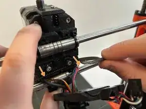
Loosen the 2.5mm X 18mm and 2.5mm X 30mm socket head screws that hold the belt in. You do not need to remove these screws.
-
Remove the belt from the belt grips by pulling the belt towards you.
-
Un-feed the belt from its track. The belt should now be removed.
-
-
-
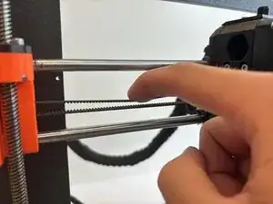
With the extruder assembly positioned in the center of the X-axis rails, press the top of the belt with moderate pressure. The top of the belt should not be able to touch the bottom of the belt.
-
-
-
Orient the printer so that the screen is facing you.
-
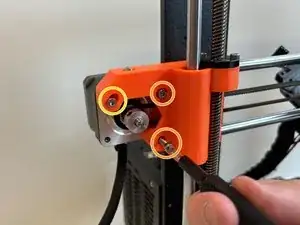
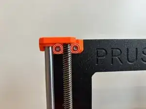
Remove the two 2.5mm X 10mm socket head screws that secure the Z-axis rod and screw bracket. Do this for both brackets.
-
-
-
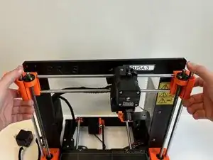
Place the X-axis carriage on the build plate and orient it so that the front of the extruder assembly is facing you.
-
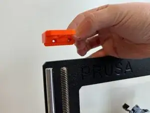
Hold the X-axis rods and pull the rod mounting bracket off of the right side of the carriage assembly.
-
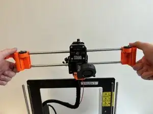
Carefully slide the extruder assembly to the right off of the X-axis rods.
-
-
-
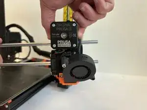
Place the front of the extruder assembly on the build plate so you can access the back.
-
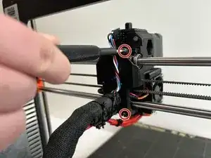
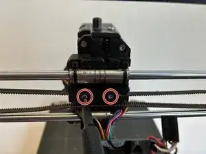
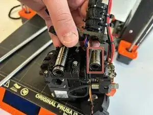
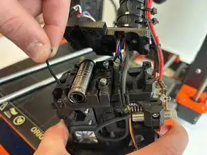
Locate the X-axis bearings on the back of the extruder assembly.
-
Remove the lower bearing; it is not secured by zip ties.
-
-
-
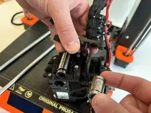
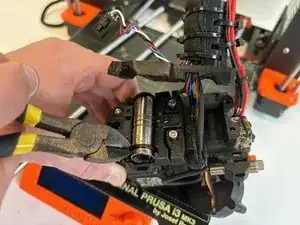
Use the side cutters to cut the existing zip ties.
-
Pull the zip ties out of the housing and discard.
-
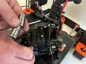
Remove the top two bearings from the extruder assembly.
-
-
-
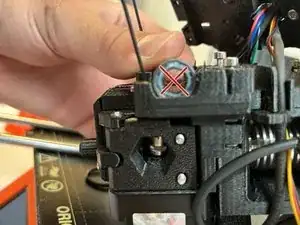
When reinstalling the X-axis bearings, the balls inside the bearings should form a diagonal "X", not a vertical "+".
-
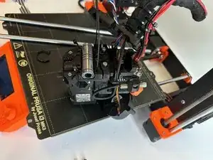
To reassemble your device, follow these instructions in reverse order. Use steps 10 and 11 for reference.