Introduction
This guide shows how to remove and replace the left speaker on your PlayStation Portal.
-
-
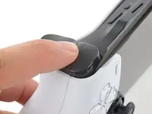
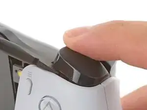
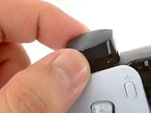
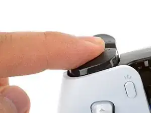
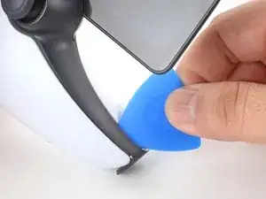
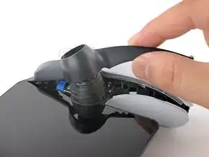
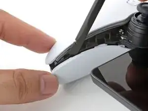
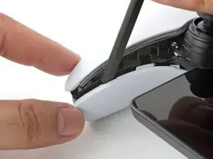
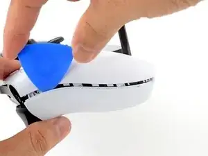
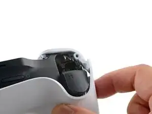
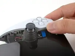
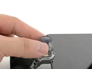
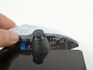
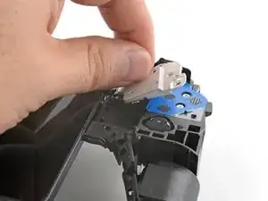
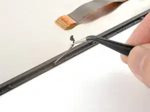
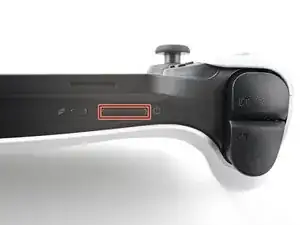
Rest a finger over the L1 bumper to prevent it from flying off when you pry.
-
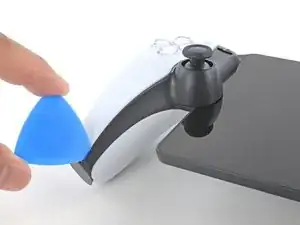
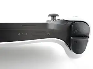
Insert the flat end of a spudger between the top edge of the bumper and the white shell.
-
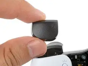
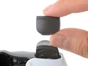
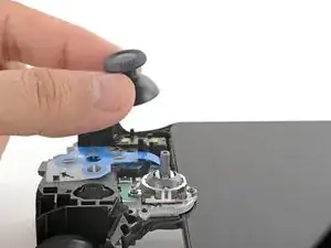
Pry up to unclip the bumper.
-
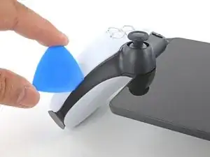
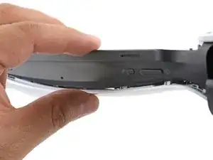
Slide the spudger along the seam to release any remaining clips.
-
-
-
Align the bumper into its slot.
-
Use a finger to press the bumper down firmly until it clicks into place.
-
-
-
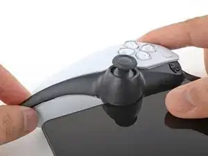
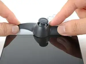
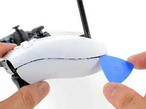
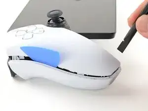
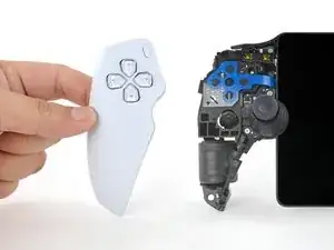
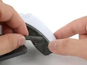
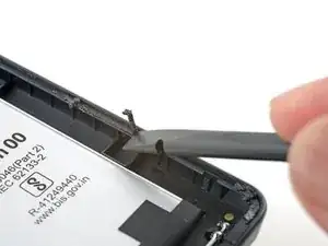
Insert the tip of an opening pick underneath the left joystick trim strip, where it wraps below the grip.
-
Twist the opening pick to release the bottom clip.
-
-
-
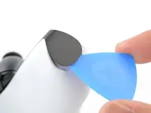
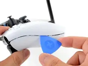
Insert the tip of an opening pick underneath the outer edge of the trim strip.
-
Slide the opening pick along the edge to release the clips.
-
-
-
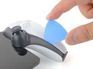
Insert the tip of an opening pick under the inner edge of the strip.
-
Slide the opening pick along the edge to release the clips.
-
-
-
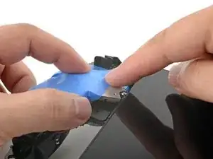
Use your fingers to align and clip the top edge in place.
-
Firmly press along the remaining edges to clip the strip in place.
-
-
-
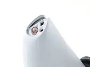
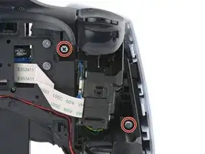
Use a Phillips screwdriver to remove the two 6.5 mm‑long screws at the bottom tips of each grip.
-
-
-
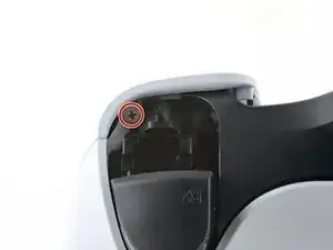
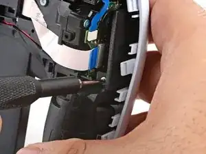
Use a Phillips screwdriver to remove the two 6.5 mm‑long screws securing the top corners of the shell.
-
-
-
Push the flat edge of a spudger into the back shell's left, inner seam.
-
Keep the spudger inserted in the seam.
-
-
-
Insert the tip of an opening pick into the shell's left, outer seam.
-
Slide the pick along the seam to release the clips securing the edge.
-
Keep a pick in the seam to prevent the shell from clipping back together.
-
-
-
Repeat the previous three steps on the right side of the Portal to release the clips along the right edge.
-
-
-
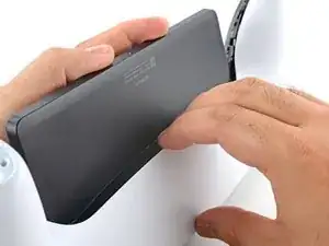
Carefully flip your Portal over.
-
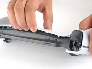
Grasp the top edge of the back shell, near a corner.
-
Gently pull the top edge away until you feel the clips release in that corner.
-
-
-
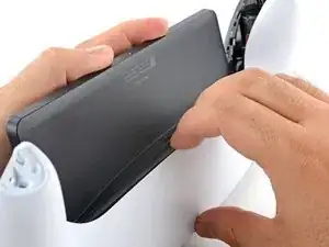
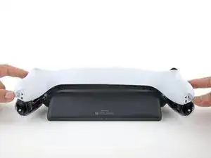
Grasp the bottom edge of the back shell, near the center.
-
Pull away with firm force to release the clips securing the bottom edge.
-
-
-
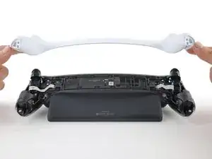
Align the corners near the trigger buttons first.
-
Firmly press around the entire perimeter to clip the shell back in place.
-
-
-
Use a Phillips screwdriver to remove the two 6.5 mm‑long screws securing the left grip shell to the Portal.
-
-
-
Grasp the top edge of the grip shell and twist it slightly outwards (away from the screen) to release the inner clips.
-
-
-
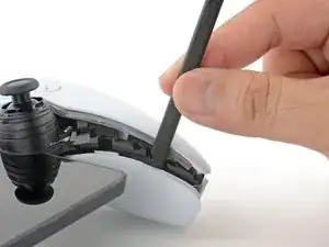
Insert the flat edge of a spudger underneath the inner edge of the grip shell, near the vibration motor.
-
Twist the spudger along the edge to unclip the bottom portion of the grip shell.
-
Remove the left grip shell.
-
-
-
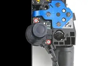
Use a Phillips screwdriver to remove the two 6.5 mm‑long screws securing the left joystick cover.
-
-
-
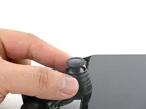
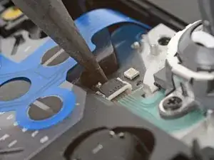
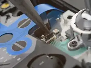
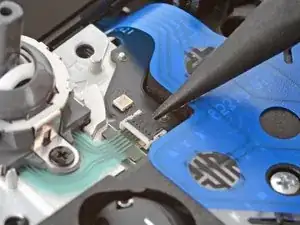
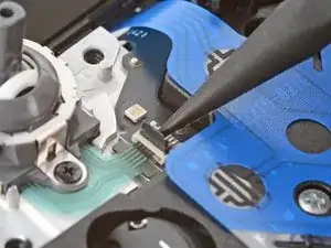
Use the point of a spudger to flip up the black lock tab on the left joystick's ZIF connector.
-
-
-
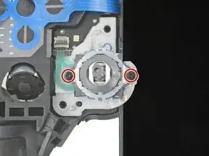
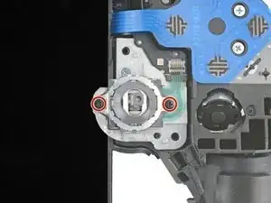
Use a Phillips screwdriver to remove the two 2.9 mm‑long screws securing the joystick module to the Portal.
-
-
-
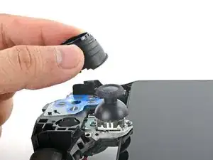
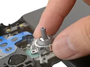
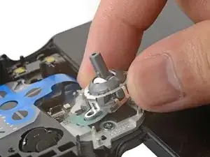
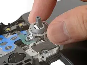
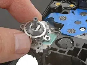
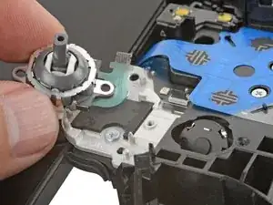
Shift the joystick module so that the flex cable slides out of its socket.
-
Remove the left joystick.
-
-
-
Use a Phillips screwdriver to remove the two 6.5 mm‑long screws securing the right grip shell to the Portal.
-
-
-
Grasp the top edge of the grip shell and twist it slightly outwards (away from the screen) to release the inner clips.
-
-
-
Insert the flat edge of a spudger underneath the inner edge of the grip shell, near the vibration motor.
-
Twist the spudger along the edge to unclip the bottom portion of the grip shell.
-
Remove the right grip shell.
-
-
-
Use a Phillips screwdriver to remove the two 6.5 mm‑long screws securing the right joystick cover.
-
-
-
Use the point of a spudger to flip up the black lock tab on the right joystick's ZIF connector.
-
-
-
Use a Phillips screwdriver to remove the two 2.9 mm‑long screws securing the joystick module to the Portal.
-
-
-
Shift the joystick module so that the flex cable slides out of its socket.
-
Remove the right joystick.
-
-
-
Use a Phillips screwdriver to remove the four 6.5 mm‑long screws (two on each side) securing the two joystick brackets to the Portal.
-
-
-
Carefully flip the right bracket over so that it no longer blocks the edge of the screen.
-
Repeat the process for the left bracket.
-
-
-
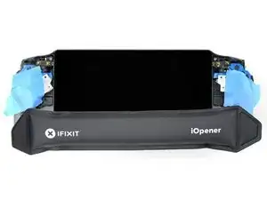
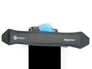
Heat an iOpener and apply it to the bottom edge of the screen for two minutes to soften the adhesive.
-
-
-
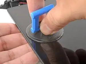
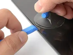
Place your fingers underneath the bottom edge of the Portal to keep it steady.
-
Apply a suction handle to the center of the bottom edge, as close to the edge as possible.
-
-
-
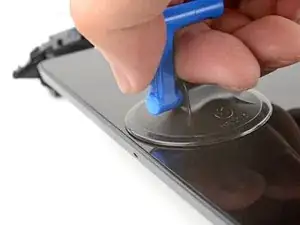
Pull up on the suction handle with strong, steady force.
-
Press the edge of an opening tool downwards into the seam to create an initial gap.
-
Insert the tip of an opening pick into the gap.
-
-
-
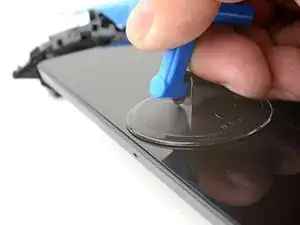
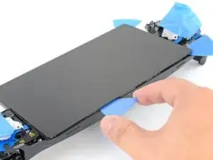
Pull up on the suction handle with strong, steady force to create a gap between the screen and frame.
-
Insert the tip of an opening pick into the gap.
-
-
-
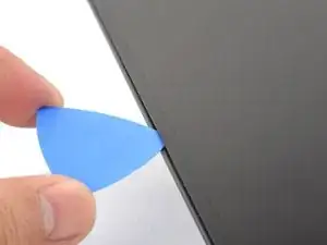
Angle the opening pick downwards to a 45° angle.
-
Insert the opening pick deeper into the seam until the pick can stay in place by itself.
-
-
-
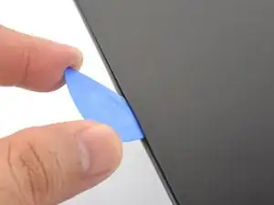
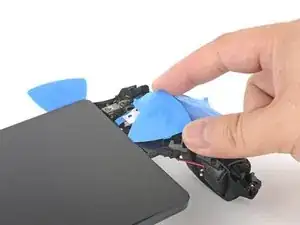
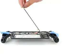
Slide the opening pick along the bottom edge to slice through the adhesive.
-
Leave the opening pick in the bottom left corner to prevent the adhesive from resealing.
-
-
-
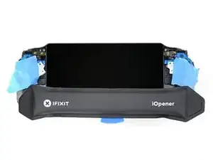
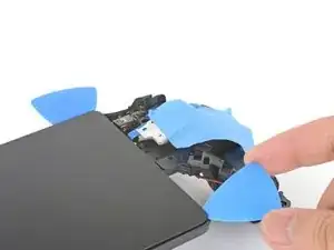
Repeat the heating and slicing procedure around the left and top edges of the screen. Leave an opening pick in each corner to prevent the adhesive from resealing.
-
-
-
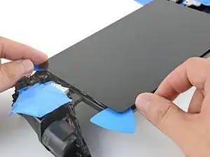
Use an iOpener to heat the right edge of the screen for one minute.
-
Use an opening pick to slice along the right edge.
-
-
-
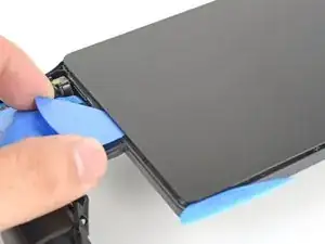
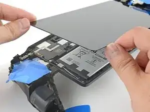
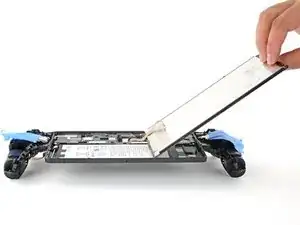
Grasp the left edge of the screen near the corners and lift it slightly to separate any remaining adhesive.
-
-
-
Swing the left edge of the screen over the right and rest the flipped screen on top of the Portal.
-
-
-
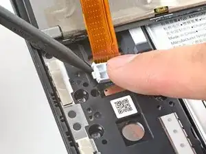
Rest a finger on top of the display cable bracket to prevent it from flying off when you pry.
-
Insert the point of a spudger underneath a corner of the bracket and pry it up.
-
Remove the bracket.
-
-
-
Remove large chunks of adhesives with the flat edge of a spudger or tweezers.
-
Use high concentration isopropyl alcohol (>90%) to remove any remaining residue. Wipe in one direction with a lint-free cloth or coffee filter until all the adhesive residue is gone.
-
Apply strips of double-sided tape such as Tesa tape to the screen perimeter to reattach the screen.
-
-
-
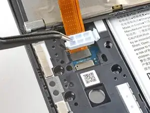
Use a Phillips screwdriver to remove the eight 6.5 mm‑long screws securing the motherboard cover to the Portal.
-
-
-
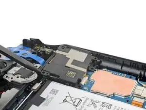
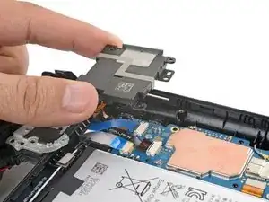
Insert the flat edge of a spudger under the top-right corner of the motherboard cover.
-
Pry up to release the clips securing the corner.
-
-
-
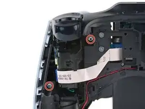
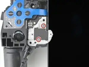
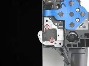
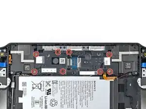
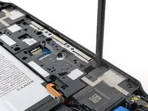
Use a Phillips screwdriver to remove the three screws securing the left speaker to the Portal:
-
Two 2.9 mm‑long screws
-
One 6.5 mm‑long screw
-
-
-
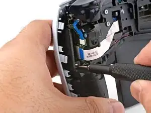
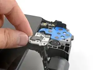
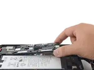
Insert the point of a spudger underneath the bottom left corner of the left speaker.
-
Pry up and remove the left speaker.
-


To reassemble your device, follow these instructions in reverse order.
Take your e-waste to an R2 or e-Stewards certified recycler.
Repair didn’t go as planned? Try some basic troubleshooting, or ask our Answers community for help.