Introduction
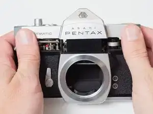
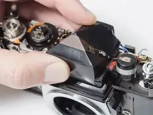
Removing the viewfinder is part of the longer disassembly process for the Pentax Spotmatic. It is also recommended for cleaning or replacing components of the viewfinder.
-
-
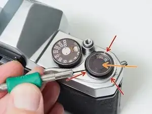
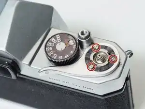
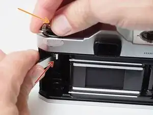
Loosen three grub screws. Do not remove them from the frame counter cover.
-
Lift off frame counter cover.
-
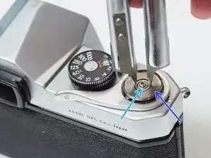
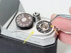
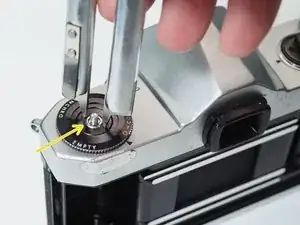
Remove one 2.5 mm flat head screw. It is reverse or left-hand threaded.
-
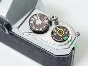
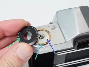
Remove the frame counter dial.
-
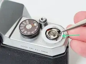
Remove the retaining nut using a spanner wrench. A pair of fine tipped nippers can also work.
-
Remove the dial seat.
-
-
-
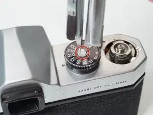
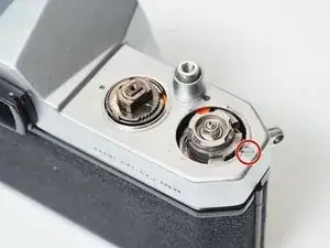
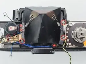
Remove three 2.3 mm flat head screws.
-
Use a pick to rotate the retaining washer until the lobed sections are free.
-
Lift off the advance lever.
-
Remove the plastic shim washer.
-
-
-
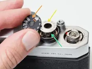
Remove one 2.8 mm pin head screw.
-
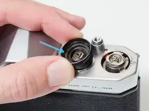
Remove the shutter speed dial.
-
Remove the ISO dial.
-
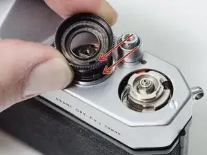
Remove the internal spring.
-
Remove the dial housing.
-
-
-
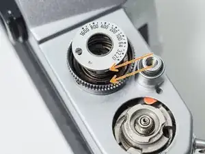
The hole in the dial housing needs to go over the tab on the speed resistor.
-
The tab on the ISO dial needs to mate with the hole in the dial housing.
-
It can be difficult to line everything up while compressing the spring and installing the center screw. Be patient.
-
-
-
Place a thin, sturdy tool in the spindle fork.
-
Unscrew the rewind knob.
-
Use a spanner wrench to unscrew the retaining nut.
-
Remove the film reminder
-
Remove the spring washer.
-
Remove the friction plate.
-
-
-
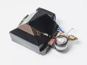
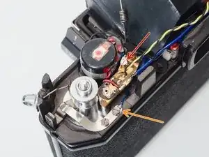
Unscrew or unsolder one black wire. This is the main power coming from the meter switch on the side of the mirror box.
-
Unscrew one blue wire. This is the ground wire that connects the meter circuit to the body of the camera.
-
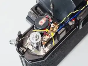
Unsolder one yellow and one black wire from the speed resistor.
-
To reassemble your device, follow these instructions in reverse order.