
Introduction
Removing the top cover of the camera is often the first step in a larger repair. It is also useful for performing basic adjustments like tuning the shutter speeds and calibrating the light meter. This guide will detail how to disassemble the necessary user controls and remove the top cover of a Pentax Spotmatic.
Tools
-
-
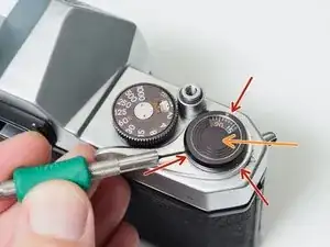
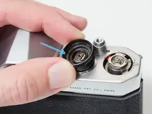
Loosen three grub screws. Do not remove them from the frame counter cover.
-
Lift off frame counter cover.
-
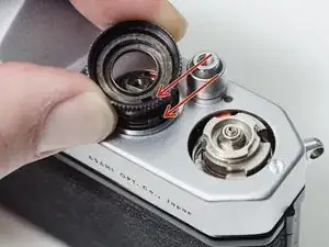
Remove one 2.5 mm flat head screw. It is reverse or left-hand threaded.
-
Remove the frame counter dial.
-
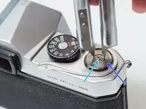
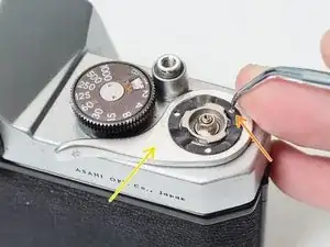
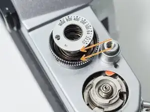
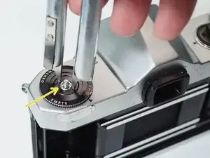
Remove the retaining nut using a spanner wrench. A pair of fine tipped nippers can also work.
-
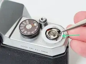
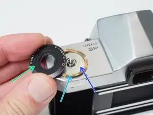
Remove the dial seat.
-
-
-
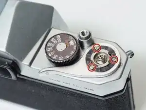
Remove three 2.3 mm flat head screws.
-
Use a pick to rotate the retaining washer until the lobed sections are free.
-
Lift off the advance lever.
-
Remove the plastic shim washer.
-
-
-
Remove one 2.8 mm pin head screw.
-
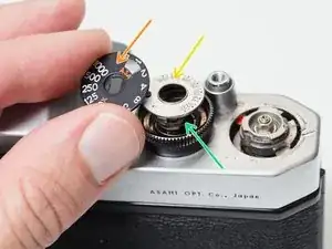
Remove the shutter speed dial.
-
Remove the ISO dial.
-
Remove the internal spring.
-
Remove the dial housing.
-
-
-
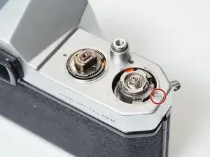
The hole in the dial housing needs to go over the tab on the speed resistor.
-
The tab on the ISO dial needs to mate with the hole in the dial housing.
-
It can be difficult to line everything up while compressing the spring and installing the center screw. Be patient.
-
-
-
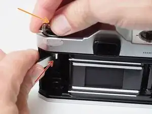
Place a thin, sturdy tool in the spindle fork.
-
Unscrew the rewind knob.
-
Use a spanner wrench to unscrew the retaining nut.
-
Remove the film reminder
-
Remove the spring washer.
-
Remove the friction plate.
-
To reassemble your device, follow these instructions in reverse order.