
Introduction
During an exposure, the mirror box mechanism moves the mirror from the viewing position to the taking position, stops down the lens aperture, then returns the mirror to the viewing position. Over time, old lubrication migrates to unwanted areas, surfaces oxidize and corrode and dirt and grime builds up on moving parts. Eventually, parts may not move as they were intended resulting in various malfunctions. Disassembling and cleaning the mirror box mechanism can resolve issues with winding and stuck mirrors. The following guide will detail the disassembly process and recommend basic cleaning and lubrication methods.
There is some variation in the mirror box mechanisms between Spotmatics from different production runs. Your camera may look slightly different than the one presented here.
-
-
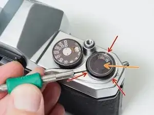
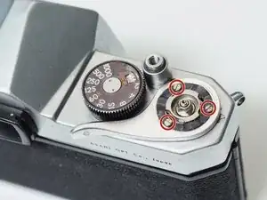
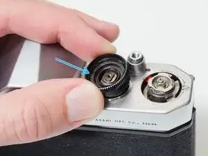
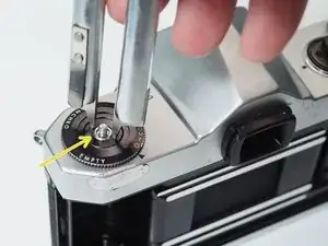
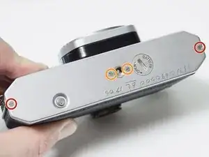
Loosen three grub screws. Do not remove them from the frame counter cover.
-
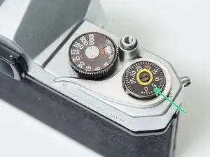
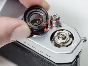
Lift off frame counter cover.
-
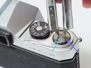
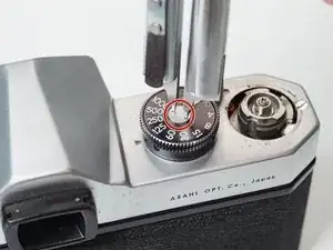
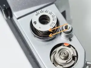
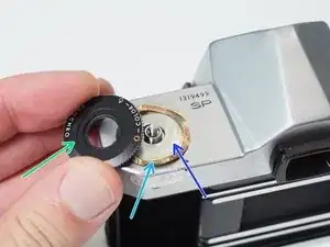
Remove one 2.5 mm flat head screw. It is reverse or left-hand threaded.
-
Remove the frame counter dial.
-
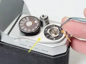
Remove the retaining nut using a spanner wrench. A pair of fine tipped nippers can also work.
-
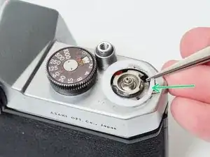
Remove the dial seat.
-
-
-
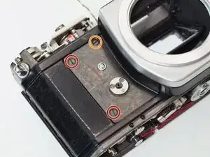
Remove three 2.3 mm flat head screws.
-
Use a pick to rotate the retaining washer until the lobed sections are free.
-
Lift off the advance lever.
-
Remove the plastic shim washer.
-
-
-
Remove one 2.8 mm pin head screw.
-
Remove the shutter speed dial.
-
Remove the ISO dial.
-
Remove the internal spring.
-
Remove the dial housing.
-
-
-
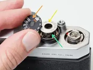
The hole in the dial housing needs to go over the tab on the speed resistor.
-
The tab on the ISO dial needs to mate with the hole in the dial housing.
-
It can be difficult to line everything up while compressing the spring and installing the center screw. Be patient.
-
-
-
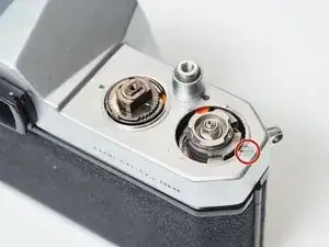
Place a thin, sturdy tool in the spindle fork.
-
Unscrew the rewind knob.
-
Use a spanner wrench to unscrew the retaining nut.
-
Remove the film reminder
-
Remove the spring washer.
-
Remove the friction plate.
-
-
-
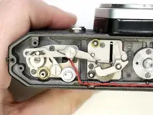
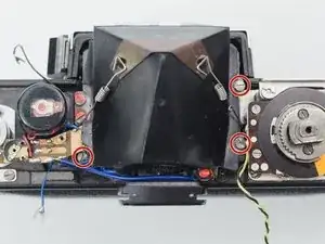
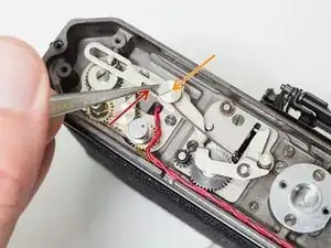
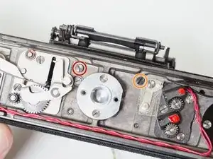
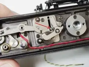
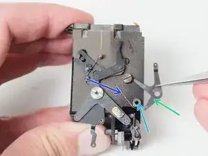
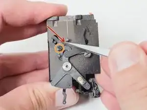
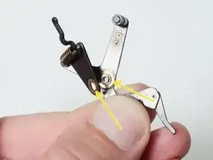
This is an example of a properly functioning mirror charging mechanism.
-
The large gear on the far left is driven by the film advance lever on top of the camera.
-
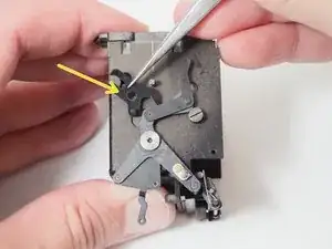
The long silver lever is the mirror charging lever. It pushes the black bar to the top of the slot when the camera is wound, which charges the main mirror spring.
-
The lever on the right holds the black bar in place while the camera is cocked and ready to shoot.
-
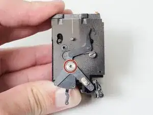
At the end of an exposure, the large black gear pushes the release lever, returning the mirror to the viewing position.
-
-
-
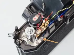
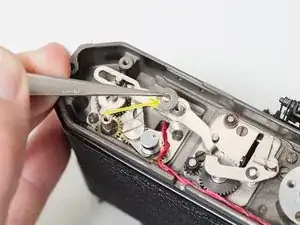
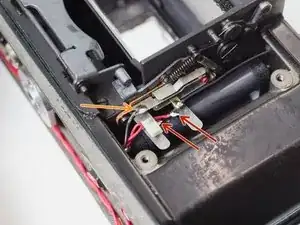
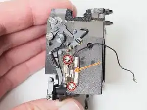
Unscrew or unsolder one black wire. This is the main power coming from the meter switch on the side of the mirror box.
-
Unscrew one blue wire. This is the ground wire that connects the meter circuit to the body of the camera.
-
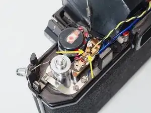
Unsolder one yellow and one black wire from the speed resistor.
-
-
-
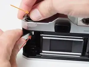
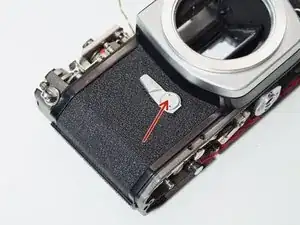
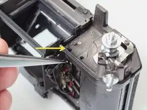
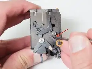
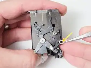
Remove cover screw using a spanner wrench.
-
Remove the self timer lever. The internal mechanism will unwind past the installed position when the lever is removed.
-
-
-
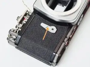
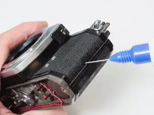
Apply isopropyl alcohol to the edge of the leatherette covering to soften the adhesive.
-
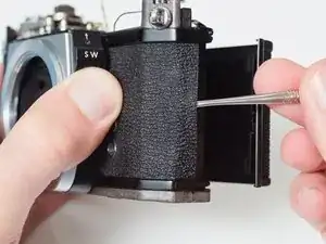
Use a dull scraper to get under the edge of the leatherette and begin peeling it off.
-
Fully remove the leatherette covering from both sides of the camera.
-
If the self timer lever can't be removed, the leatherette can be peeled away just enough to access the screws.
-
-
-
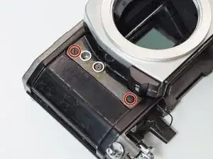
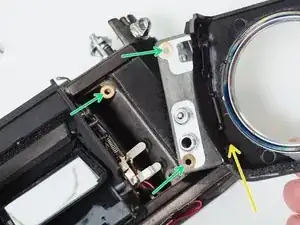
Remove four 4.6 mm flat head screws.
-
Remove one 4.3 mm flat head screws.
-
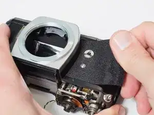
Lift off front lens board.
-
Note the position and number of shim washers at each screw location. They need to be installed in the same positions during reassembly.
-
-
-
Unhook mirror return spring.
-
Unscrew one 4.8 mm flat head shoulder screw.
-
Remove keyed washer.
-
-
-
Unsolder two red wires. These connect to the X-sync contact.
-
Unsolder one black wire. This connects to the battery compartment contact.
-
Pull black meter wire through the whole in the chassis.
-
-
-
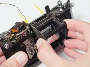
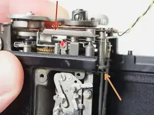
Remove one 4.3 mm flat head screw.
-
Remove one 4.5 mm flat head shoulder screw.
-
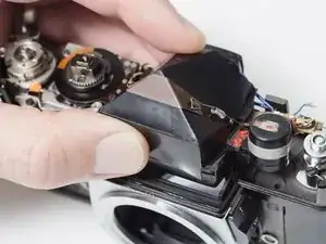
Lift mirror box up and over posts on the back of the camera. The posts can be removed for easier removal and installation if necessary.
-
-
-
The shutter should be released before installing the mirror box.
-
The mirror charging lever needs to be behind the mirror actuator lever coming from the mirror box.
-
The post from the shutter release shaft should be above the mirror release lever on the mirror box.
-
-
-
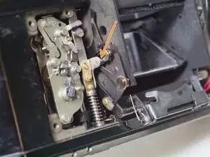
With the mirror box removed, the shutter can be fired by pushing the shutter release bar...
-
and releasing the opening curtain latch
-
-
-
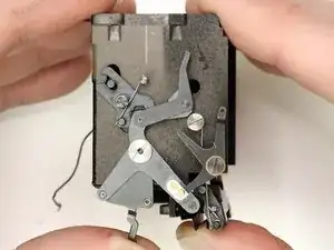
A lever on the camera body charges the main mirror spring.
-
The shutter release pushes the mirror release lever.
-
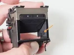
The mirror flips up into the taking position and the stop down plate is pushed forward.
-
The arm extending from the top of the mechanism is the opening curtain striker. It releases the opening curtain latch located on the camera body and begins the exposure of the shutter.
-
The mirror return spring (also on the camera body) pulls the mirror back down to the viewing position.
-
-
-
Unhook bias spring.
-
Remove one 5.0 mm flat head shoulder screw.
-
Remove shim washer.
-
Remove mirror release latch.
-
Remove bushing.
-
Remove bias spring.
-
-
-
Remove one X mm flat head shoulder screw.
-
You may need to hold this screw in the mirror box in place while unscrewing.
-
Note and remove two shim washers.
-
To reassemble your device, follow these instructions in reverse order.
Clean all removed parts and mounting points with isopropyl alcohol. High friction surfaces and/or latching points should be lubricated with a thick molybdenum disulfide grease. Quickly moving pivots can be left dry, no further lubrication is necessary.