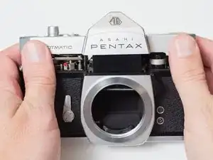
Introduction

  1. E2QAiO21VBroZvdK
    E2QAiO21VBroZvdK
    HtiHTlhXHKqHNJiu
    UBwa6gSyQnIeqSSp
    • Loosen three grub screws. Do not remove them from the frame counter cover.

    • Lift off frame counter cover.

    • Remove one 2.5 mm flat head screw. It is reverse or left-hand threaded.

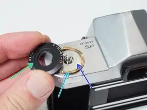
    • Remove the frame counter dial.

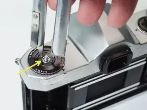
    • Remove the retaining nut using a spanner wrench. A pair of fine tipped nippers can also work.

    • On some Spotmatics, this nut may be reverse threaded. Work carefully.

    • Remove the dial seat.

  2. ykLyBilSPAimIExt
    ykLyBilSPAimIExt
    TD24kVJyvU1QE2xX
    RS1wZqfBa6iCI24M
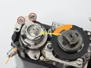
    • Remove three 2.3 mm flat head screws.

    • Use a pick to rotate the retaining washer until the lobed sections are free.

    • Lift off the advance lever.

    • Remove the plastic shim washer.

  3. HdH4KsiPcwq4Jaix
    HdH4KsiPcwq4Jaix
    yX6cd1TJyYp2udGV
    MqBZbvJXINOQOFxX
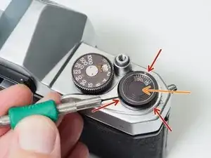
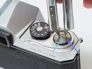
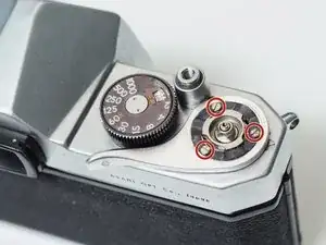
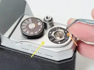
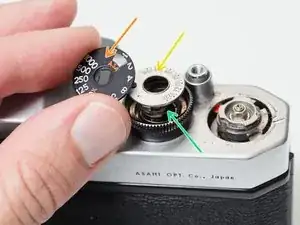
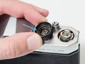
    • Remove one 2.8 mm pin head screw.

    • The dial assembly is spring loaded. Keep two fingers on top of the dial as you are loosening the screw to prevent it from popping off.

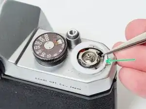
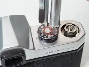
    • Remove the shutter speed dial.

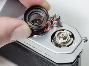
    • Remove the ISO dial.

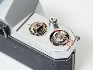
    • Remove the internal spring.

    • Remove the dial housing.

  4. MVhCVdO5LtIpTywL
    MVhCVdO5LtIpTywL
    VvVxUmqBvahkZiep
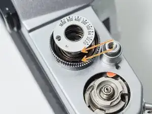
    • The hole in the dial housing needs to go over the tab on the speed resistor.

    • The tab on the ISO dial needs to mate with the hole in the dial housing.

    • It can be difficult to line everything up while compressing the spring and installing the center screw. Be patient.

  5. Qkf4Ap1wRjcCLIo1
    Qkf4Ap1wRjcCLIo1
    kMrnDnw1OHCYAFZl
    o3AvlrojUrPQ4iR1
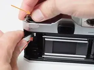
    • Place a thin, sturdy tool in the spindle fork.

    • Unscrew the rewind knob.

    • Use a spanner wrench to unscrew the retaining nut.

    • Remove the film reminder

    • Remove the spring washer.

    • Remove the friction plate.

  6. BREZZRE5DjFUCCoH
    BREZZRE5DjFUCCoH
    MXXLXNtVRwpNwblc
    • Remove one 3.0 mm flat head screw.

    • Remove top cover.

  7. Y2XWuWKCuUBl2R4u
    • Remove one 5.3 mm flat head screw and attached spring.

    • Remove one 9.1 mm flat head screw.

    • Remove the shutter ready indicator.

    • Installation Notes: The lever is easily bent and may need adjustment during final assembly. Temporarily replace the top cover and check that it changes correctly from black to orange in the indicator window. Reshape as necessary.

  8. vhOKSUYBuQY36Ivx
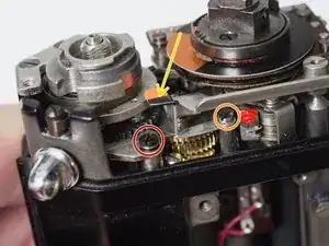
    • Remove two 3.4 mm flat head screws from the wind stopper.

    • The wind driver will unwind when the stopper is removed.

    • Remove the wind spring from the retention post.

    • Remove the wind driver.

  9. dKQGfydMMN2x6mQW
    dKQGfydMMN2x6mQW
    JeriRGntVIKBrrBZ
    3UdlYEBjuscYWitl
    • Move the ratchet teeth outward such that they won't engage with the main wind gear but are still held in place by the bias springs.

    • Install the wind driver.

    • Hook the wind spring on its retention post.

    • Turn the wind driver counter-clockwise until the wind spring drops inside the corner of the camera chassis.

    • Install the wind stopper plate.

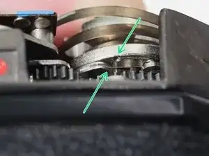
    • Push the ratchet teeth in to engage them with the main wind gear. The bias springs should look like this when properly installed.

    • The wind spring should be tight enough so it doesn't interfere with other components in the camera and loose enough to allow a full wind of the advance lever.

  10. SIGEu5lbYwhh6qVD
    SIGEu5lbYwhh6qVD
    lJENvR3CKGdyGSSH
    • Remove main wind gear.

    • Remove two 3.5 mm flat head screws.

    • Lift the support shaft slowly. The mechanism underneath is spring loaded and may jump free.

  11. nCP5X2vPkTleKZck
    nCP5X2vPkTleKZck
    IAkMGNGQ5bWTVmpD
    nJ2LiPKgNFM1uULf
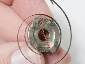
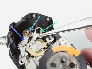
    • Hold the cap washer in place while unhooking the main spring.

    • Remove the cap washer.

    • Remove the main spring.

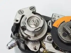
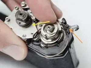
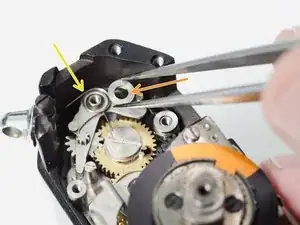
    • Remove the ratchet pawl.

    • Remove the shim washer.

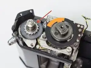
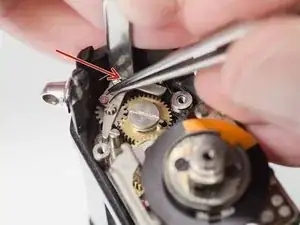
    • Remove the counter advance gear and lever.

    • Installation Notes: Hold the cap washer while tensioning the main spring. You may need to install the support shaft assembly to hold the counter mechanism in place.

    On early Spotmatics, the frame counter plate mounting screw has a right-hand thread. Underneath is a clock spring that pops off and must be rewound when reassembling. On later Spotmatics, the frame counter plate mounting screw has a left-hand thread.

    On early Spotmatics, the topcover mounting screw near the frame counter is on the right side of the topcover. On later models, it is under the frame counter.

    Gerjan van Oosten -

Conclusion

To reassemble your device, follow these instructions in reverse order.

Sam Gustafson

Member since: 02/09/22

6626 Reputation

0 comments