Introduction
Cleaning the shutter block can resolve issues with uneven exposure and ever recover a frozen shutter. The assembly contains two rubber bumpers that degrade over time and can eventually interfere with curtain travel. Cleaning up the sticky residue is usually enough to restore the shutter to proper functionality.
-
-
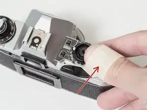
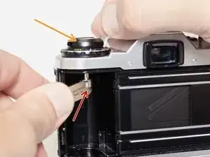
Wrap a piece of masking tape around your thumb, sticky side out.
-
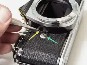
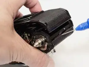
Turn the wind lever cap clockwise to remove (it is reverse threaded).
-
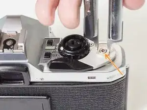
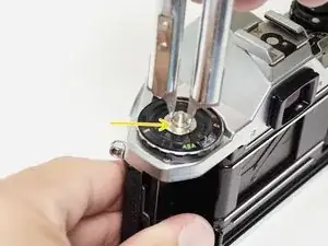
Remove the wind lever lock ring (it is also reverse threaded).
-
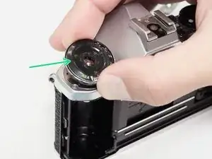
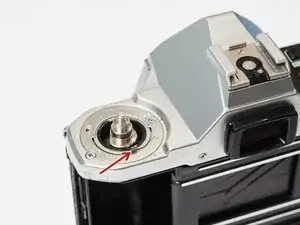
Remove the brass spring washer.
-
-
-
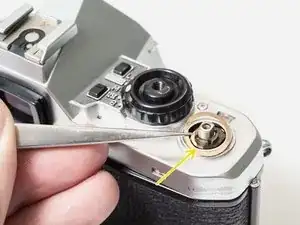
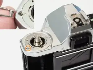
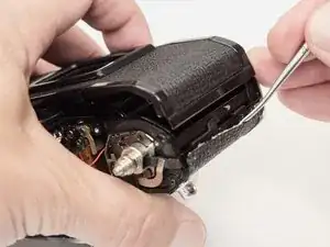
Place a tool in the fork of the rewind spindle.
-
Unscrew the rewind lever.
-
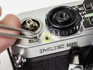
Remove the lock ring with a spanner.
-
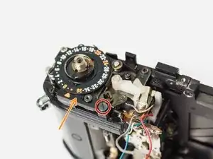
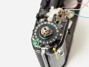
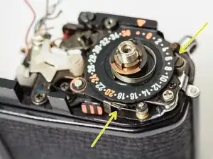
Lift off the ISO/Exposure Compensation dial.
-
-
-
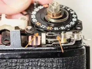
Ensure that the ISO dial couples with the tab on the resistor.
-
Turn the Exposure Compensation to 1/4x then back to 4x while gently pushing down. This will help the dial engage with the detent mechanism properly.
-
-
-
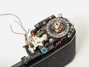
Lift off the top cover. The silver trim piece is loose and may fall away.
-
Remove loose washer.
-
-
-
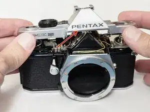
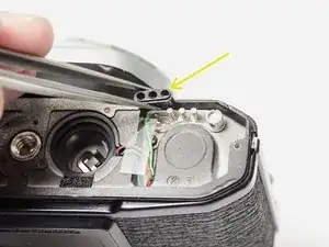
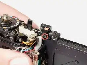
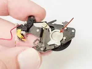
The shutter pin is loose. Make sure it is in place before installing the top cover.
-
The mode dial pin must be properly coupled with the mechanisms in the camera for it to work.
-
Set the mode dial to 'M'. Place the top cover on the camera. Move the mode dial to 'B' then back to 'M' while gently pushing down.
-
The mode dial should click into place and work properly.
-
-
-
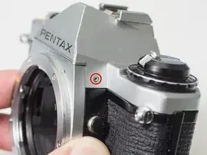
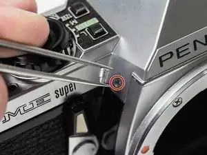
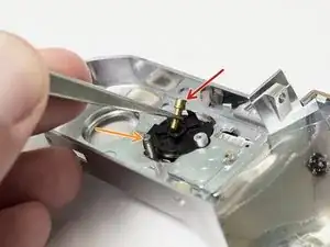
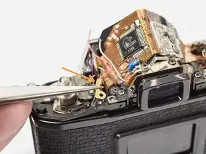
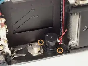
Use a spanner or tweezers to remove remove self-timer screw. It is reverse threaded.
-
Remove self-timer lever.
-
Remove black spacer.
-
Remove spring washer.
-
-
-
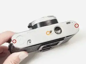
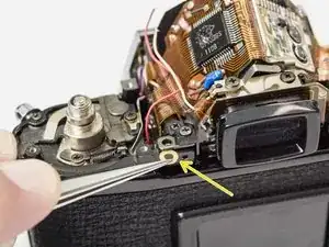
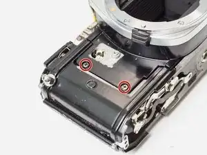
Remove two 3.0 mm #00 screws.
-
Remove one 2.1 mm #00 screw.
-
Remove loose plastic cover for motor drive pins.
-
-
-
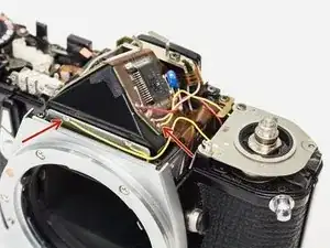
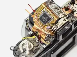
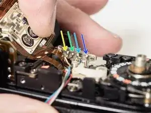
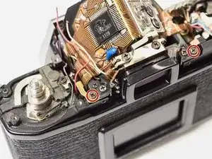
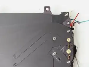
Unsolder two yellow wires.
-
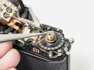
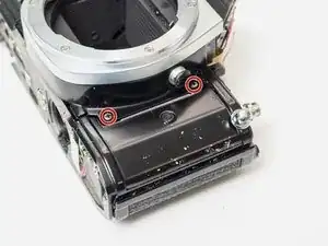
Remove one 3.0 mm #00 screw.
-
Remove one 5.9 mm flat head screw.
-
Lift off ISO resistor.
-
-
-
Unsolder the red and blue wires (positive battery). They may share a pad.
-
Unsolder one gray wire.
-
Unsolder one white wire.
-
Unsolder one brown wire.
-
Unsolder one metal contact.
-
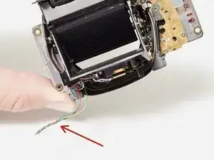
Unsolder one pink wire.
-
-
-
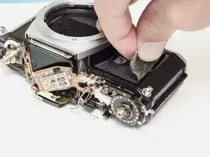
Apply isopropyl alcohol to soften the leatherette adhesive.
-
Use a dull scraper to left the edge of the covering.
-
Peel the leatherette away and remove it from both sides of the camera front.
-
-
-
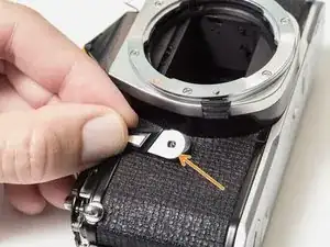
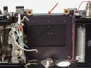
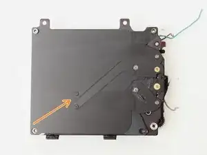
Remove two 3.4 mm #00 screws.
-
Remove flex PCB retainer.
-
Remove shim washers. Note the location (left or right) and install in the same positions during reassembly.
-
-
-
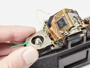
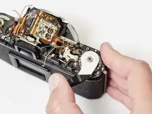
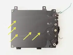
Temporarily replace the advance lever and cock the shutter.
-
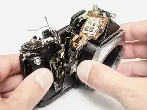
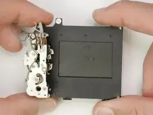
Gently lift the front block away from the camera body. Move slowly and look for wire snags.
-
-
-
Cock the shutter on the camera body. The mirror box should be uncharged before installation.
-
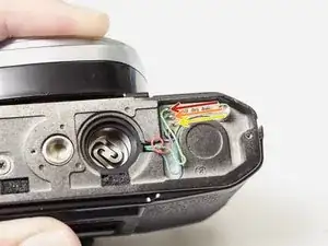
Twist the three motor drive wires together to easily insert them through the bottom of the camera.
-
Carefully track wire routing during installation. Make sure nothing is getting pinched and that all wires are accessible for resoldering.
-
Once the front block is in place, check the mechanical speeds of the shutter before completing the reassembly. The mirror and shutter should function normally.
-
-
-
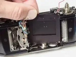
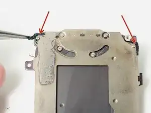
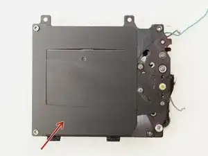
Remove one 5.1 mm flat head screw.
-
Remove frame number indicator.
-
Unhook spring.
-
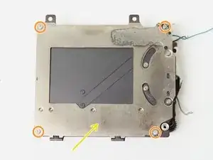
Remove one 3.9 mm #00 screw.
-
Remove one 3.0 mm #00 screw.
-
Carefully remove frame counter assembly.
-
-
-
Make sure the silver cam is fully inserted and in the correct position.
-
Insert these levers first. Then gently work the rest of the assembly into place.
-
Make sure the bias springs are placed properly.
-
-
-
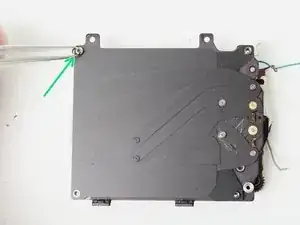
Remove shutter light seal.
-
Remove three 3.4 mm #00 screws.
-
Swing the right side of the shutter forward, then lift out.
-
-
-
Cock the shutter by pushing the lever on the bottom to the left.
-
Push the shutter release on the bottom of the shutter begin the exposure.
-
Push the white plastic lever to the right release the closing curtain.
-
Hold the white plastic lever to the right to operate the shutter at its mechanical speed, 1/125.
-
-
-
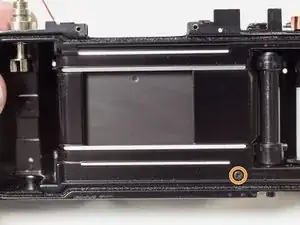
Peel off two foam light seals.
-
Remove four 2.3 mm #000 screws.
-
Remove back plate.
-
Remove top spacer.
-
-
-
Unhook helper spring.
-
Remove closing curtain linkage.
-
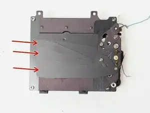
Remove five individual curtain blades.
-
-
-
Remove three individual curtain blades.
-
Remove the opening curtain linkage.
-
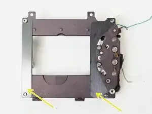
Remove two curtain guides.
-
-
-
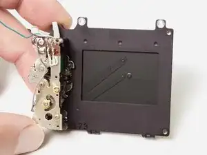
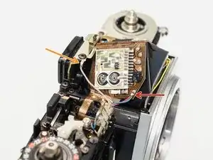
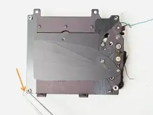
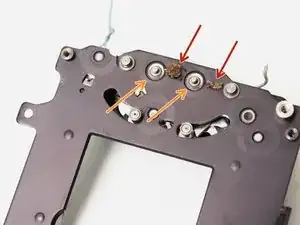
Remove two degraded rubber bumpers. Clean the surrounding area with isopropyl alcohol.
-
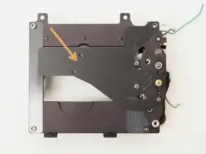
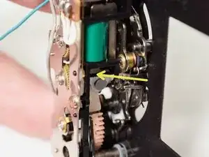
Clean the two main pivot points for the opening and closing curtains.
-
Clean the contact surface of the closing curtain electromagnet.
-


Before reinstalling the shutter block, consider replacing the old foam seals on the camera chassis. With the fragile shutter curtains removed from the camera, it's easier to scrape and clean crumbling foam. The long strip along the edge of the shutter and the seals around the edge of the film door usually need replacing.
To reassemble your device, follow these instructions in reverse order.
4 comments
Thank you for this. I think I must be crazy doing this as my first camera repair attempt. I had dirt and oil all over my shutter blades and it was jamming every shot.
I managed to get through every step... until... Trying to resolder those short wires to the mirror box (the ones with the metal ribbon amongst them, near the frame counter). If you have any tips on actually managing to do this it'd be much appreciated.
Yeah, this is the crux, the trickiest part. I like to lay the camera on the lens mount with top towards the soldering hand and the bottom towards my tweezers hand. I start with the wire closest to the lens mount. Get it in place with my tweezers as best I can, then sneak the soldering iron in just long enough to reflow the solder. Just be patient, you'll get it.
Hi. On step 29, you mention that degraded rubber parts should be removed. But do you replace them with something else? What is the consequence of removing them? A little more sound from the shutter or more wear to the shutter blades?
Honestly, I can't say what their specific purpose is other than some sort of damping. There are still two larger rubber bumpers on the bottom of the shutter that catch the edges of the curtains. Those do most of the work of stopping the blades without damaging them. I've tried both approaches, replacing the dampers with homemade parts and leaving them absent, and haven't been able to identify any differences in performance. The recommendation to leave them comes from that experience as well as comments I've seen other repairers make when they service this shutter. From what I can tell, they are supposed to be T-shaped and about 1 mm thick, in case you want to make a replacement.
In my experience it's hard to use a masking tape to unscrew the wind lever. I'd recommend a camera lens friction like this: https://www.amazon.com/Japan-Vacuum-Came...
Sergi -
Yeah, those tools are great. But I try to recommend solutions with non- specialized tools whenever possible. The only issue I've had with masking tape is that it can rip if the cover is very tight. Doubling up the wrap helps.
Sam Gustafson -