Introduction
This guide details how to remove, disassemble and clean the mirror box for the Pentax ME Super. Degraded rubber parts located in the mirror box mechanism can cause problems such as a stuck mirror and an advance lever that winds continuously. Cleaning the mirror box will resolve these issues. The repair doesn't require specialized tools but a solid understanding of how SLR cameras work is recommended.
-
-
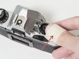
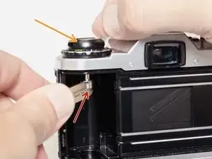
Wrap a piece of masking tape around your thumb, sticky side out.
-
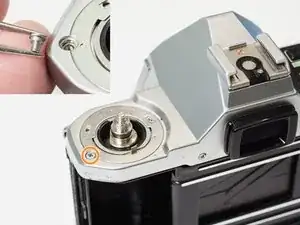
Turn the wind lever cap clockwise to remove (it is reverse threaded).
-
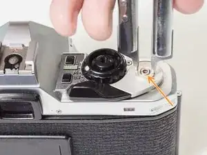
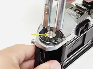
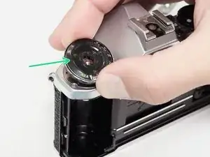
Remove the wind lever lock ring (it is also reverse threaded).
-
Remove the brass spring washer.
-
-
-
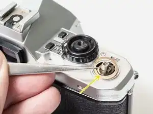
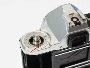
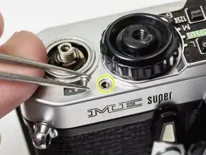
Place a tool in the fork of the rewind spindle.
-
Unscrew the rewind lever.
-
Remove the lock ring with a spanner.
-
Lift off the ISO/Exposure Compensation dial.
-
-
-
Ensure that the ISO dial couples with the tab on the resistor.
-
Turn the Exposure Compensation to 1/4x then back to 4x while gently pushing down. This will help the dial engage with the detent mechanism properly.
-
-
-
Lift off the top cover. The silver trim piece is loose and may fall away.
-
Remove loose washer.
-
-
-
The shutter pin is loose. Make sure it is in place before installing the top cover.
-
The mode dial pin must be properly coupled with the mechanisms in the camera for it to work.
-
Set the mode dial to 'M'. Place the top cover on the camera. Move the mode dial to 'B' then back to 'M' while gently pushing down.
-
The mode dial should click into place and work properly.
-
-
-
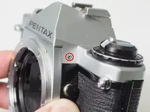
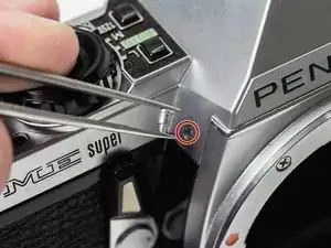
Use a spanner or tweezers to remove remove self-timer screw. It is reverse threaded.
-
Remove self-timer lever.
-
Remove black spacer.
-
Remove spring washer.
-
-
-
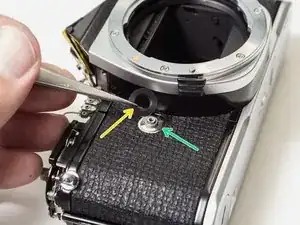
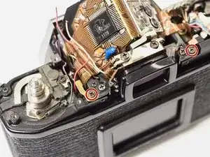
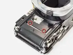
Remove two 3.0 mm #00 screws.
-
Remove one 2.1 mm #00 screw.
-
Remove loose plastic cover for motor drive pins.
-
-
-
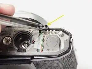
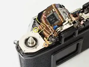
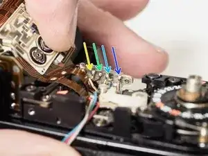
Unsolder two yellow wires.
-
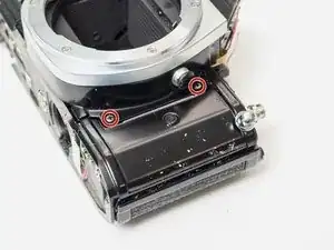
Remove one 3.0 mm #00 screw.
-
Remove one 5.9 mm flat head screw.
-
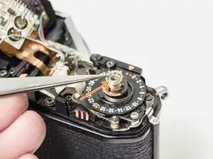
Lift off ISO resistor.
-
-
-
Unsolder the red and blue wires (positive battery). They may share a pad.
-
Unsolder one gray wire.
-
Unsolder one white wire.
-
Unsolder one brown wire.
-
Unsolder one metal contact.
-
Unsolder one pink wire.
-
-
-
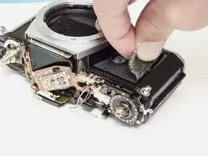
Apply isopropyl alcohol to soften the leatherette adhesive.
-
Use a dull scraper to left the edge of the covering.
-
Peel the leatherette away and remove it from both sides of the camera front.
-
-
-
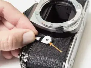
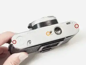
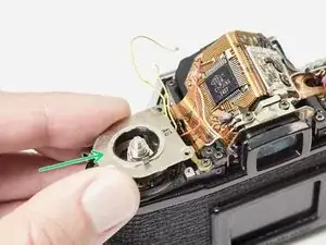
Remove two 3.4 mm #00 screws.
-
Remove flex PCB retainer.
-
Remove shim washers. Note the location (left or right) and install in the same positions during reassembly.
-
-
-
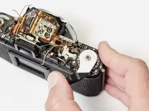
Temporarily replace the advance lever and cock the shutter.
-
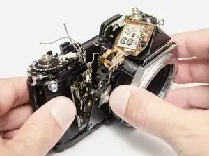
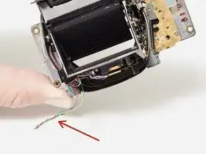
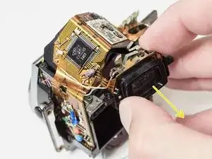
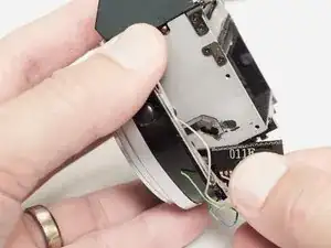
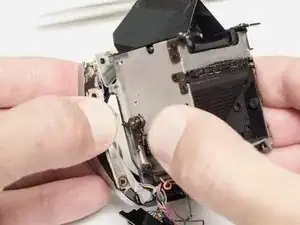
Gently lift the front block away from the camera body. Move slowly and look for wire snags.
-
-
-
Cock the shutter on the camera body. The mirror box should be uncharged before installation.
-
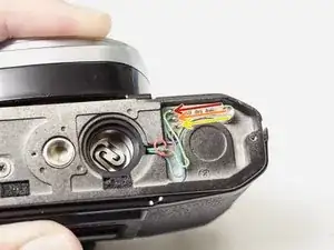
Twist the three motor drive wires together to easily insert them through the bottom of the camera.
-
Carefully track wire routing during installation. Make sure nothing is getting pinched and that all wires are accessible for resoldering.
-
Once the front block is in place, check the mechanical speeds of the shutter before completing the reassembly. The mirror and shutter should function normally.
-
-
-
Remove one 3.4 mm #00 screw.
-
Gently work the LED strip out of the slot in the mirror box until it hangs free.
-
The old dust/light seal foam will probably fall apart when the LEDs are removed. It should be replaced with new foam strips during reassembly (1.5 mm open cell foam with adhesive backing).
-
-
-
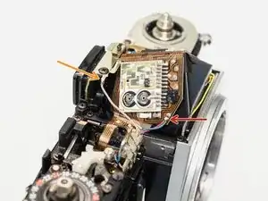
Unsolder one gray wire (flash sync).
-
Remove two 3.4 mm #00 screws.
-
Slide eye piece out of its metal frame. It is still attached to the main flex PCB.
-
-
-
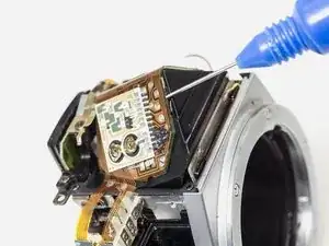
The PCB is attached to the prism with double sided tape.
-
Use isopropyl alcohol to loosen the adhesive and gently work the PCB free from the prism. Work slowly.
-
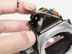
Pull the PCB out of the slot connector at the base of the mirror box.
-
-
-
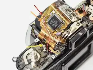
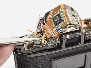
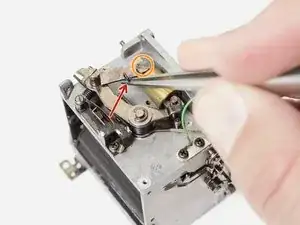
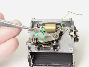
Remove one 3.0 mm #00 screw.
-
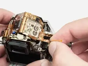
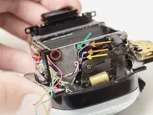
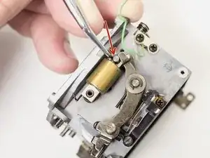
Unsolder two purple wires.
-
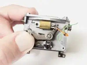
Unsolder one orange wire.
-
Unsolder one black wire.
-
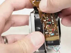
Pull PCB connector away from mirror box.
-
-
-
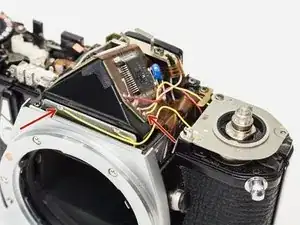
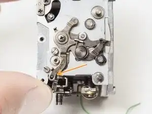
Pay close attention to the routing of the purple and gray wires on the left side.
-
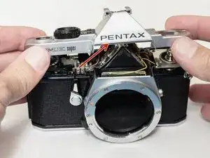
Make sure the mirror release lever (on the front plate) is properly coupled with the mirror release latch (on the mirror box).
-
-
-
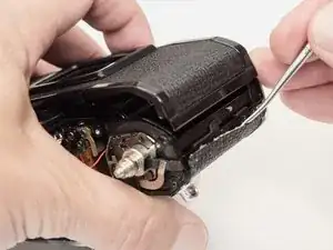
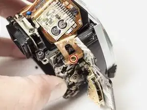
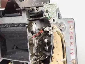
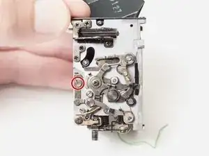
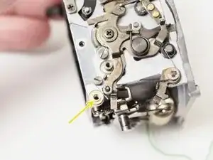
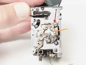
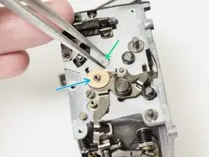
The rubber bushing under this screw causes the most problems. As it degrades it prevents the lever from moving freely leading to stuck mirrors and other malfunctions.
-
Removing this lever and cleaning out the old bushing is usually enough to get the camera functioning again.
-
Complete disassembly and cleaning out additional degraded bushings is recommended for the long term health of the camera.
-
-
-
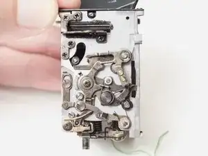
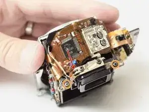
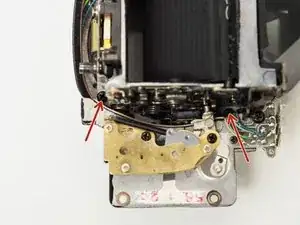
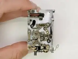
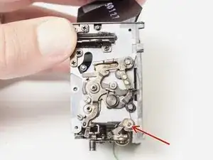
This is what a properly function mirror box should look like.
-
The mirror release latch, mirror return latch, and shutter release lever all move freely. The bias springs keep them in their ready positions.
-
The mirror is charged by pushing the large post on the bottom towards the front of the camera.
-
Push the mirror release latch up to start the cycle. The mirror should move quickly to the taking position.
-
Push the mirror return linkage and the mirror to should move to the viewing position.
-
-
-
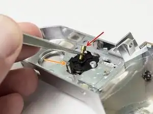
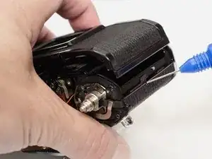
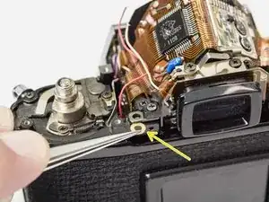
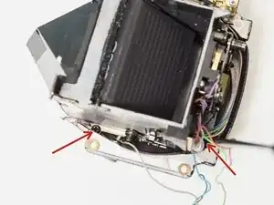
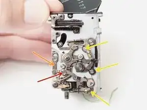
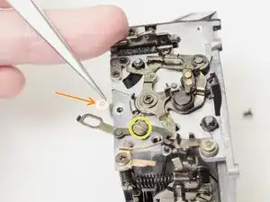
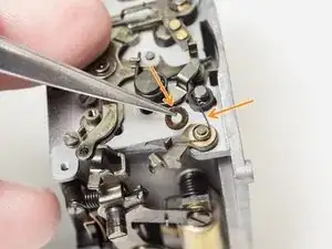
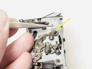
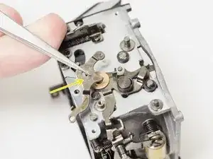
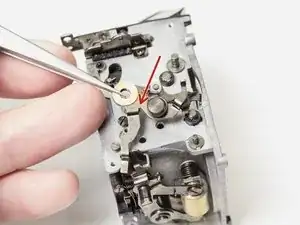
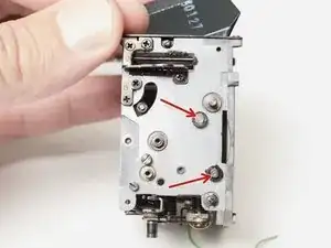
Remove one 3.2 mm flat head screw.
-
Remove one shim washer.
-
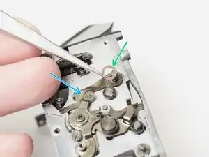
Remove one 3.5 mm flat head screw.
-
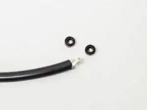
Remove degraded rubber bushing.
-
Clean thoroughly with isopropyl alcohol.
-
-
-
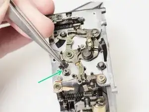
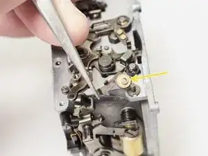
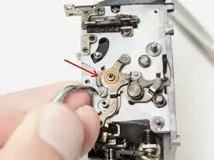
Remove one c-clip.
-
Remove mirror release latch.
-
Remove bias spring.
-
Remove shim washer.
-
Remove mirror up lever.
-
-
-
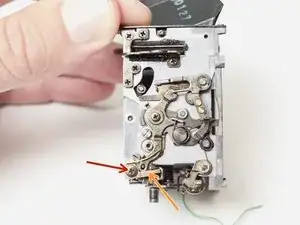
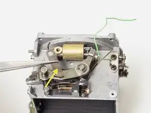
Remove tension spring.
-
Remove one 4.0 mm #00 screw and washer.
-
Remove mirror actuator lever
-
White plastic bushing is loose and may fall off.
-
Remove shim washers if present.
-
-
-
Remove the aperture coupling lever.
-
Installation Notes: Properly couple the aperture lever and the mirror actuator lever with the levers on the bottom of the mirror box.
-
-
-
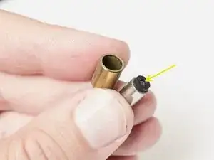
Remove two rubber bumpers and clean thoroughly with isopropyl alcohol.
-
Clean all pivots and mechanical components with isopropyl alcohol before reassembly.
-
Replacement bumpers are not required but new parts can be made from the insulation of 12 gage silicon wire.
-
-
-
Unhook tensioning spring.
-
Remove one 3.4 mm flat head screw.
-
Remove shock absorber lever.
-
Remove two washers.
-
-
-
Remove one c-clip.
-
Push mirror charge lever aside and remove air damper.
-
Separate the halves of the air damper and remove degraded rubber bumper.
-
Replace if new parts are available.
-


- To reassemble your device, follow these instructions in reverse order.
- No lubrication is required for the mirror box mechanism. All of the pivot points are left dry.
- A thick molybdenum grease can be used on the latching points to reduce wear.
In my experience it's hard to use a masking tape to unscrew the wind lever. I'd recommend a camera lens friction like this: https://www.amazon.com/Japan-Vacuum-Came...
Sergi -
Yeah, those tools are great. But I try to recommend solutions with non- specialized tools whenever possible. The only issue I've had with masking tape is that it can rip if the cover is very tight. Doubling up the wrap helps.
Sam Gustafson -