Introduction
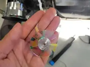
Use this guide to replace the Color Wheel on the Optoma HD72. The Optoma HD72 uses a 6-segment color wheel that includes red, green, blue, yellow, cyan, and magenta. The wide color range provided by this color combination enables the projector to create a more lifelike and immersive visual experience.
The following symptoms may indicate a problem or need for replacement with the power supply.
- Distorted Color Reproduction
- Flickering Colors
- Reduced Brightness or contrast
- Unusual Color Tints: This could be seen as an unnatural overall color to the images or video.
A few warnings to consider when dissembling this device:
- Electrical Hazards: The Optoma HD72 contains high-voltage components, so be wary of electrical shock by ensuring the device has been turned off for at least 5-10 minutes.
- The color wheel is delicate and can be easily damaged if not handled with care.
Tools
-
-
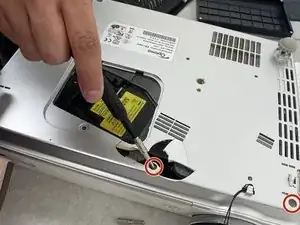
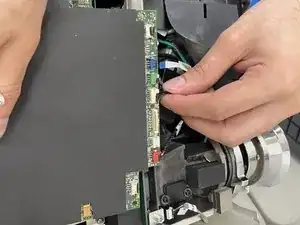
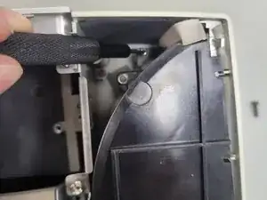
Flip the device over and slightly lift the upper case, with care not to strain the two cables.
-
Disconnect the two cables that connect the top case to the motherboard.
-
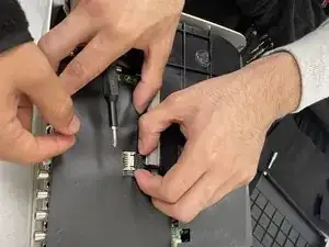
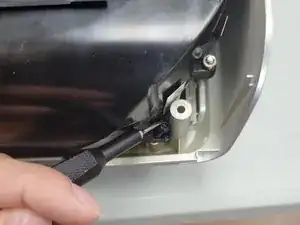
Lift the upper case up and off.
-
-
-
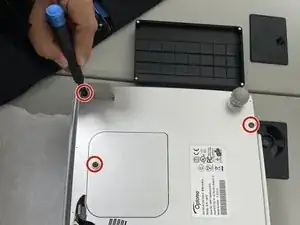
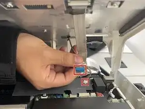
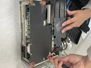
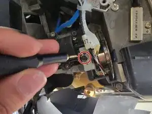
Remove the four 2 mm Phillips screws that secure the motherboard.
-
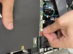
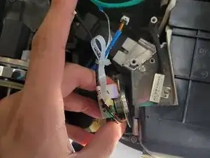
Lift the motherboard up and out of the chassis.
-
-
-
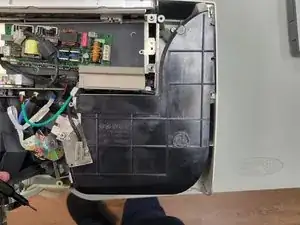
Remove the three 2 mm Phillips screws that secure the black housing.
-
Lift the black housing off.
-
-
-
Remove the single 2 mm Phillips screw that secures the color wheel.
-
Lift the color wheel up and out of its housing.
-
-
-
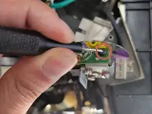
Remove the single 2 mm Phillips screw that secures the circuit board to the side of the color wheel.
-
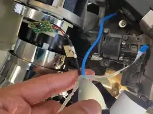
Use a sharp tool to cut the zip tie that secures the color wheel’s cables.
-
Remove the color wheel.
-
To reassemble your device, follow these instructions in reverse order.