Introduction
This is a prerequisite-only guide! This guide is part of another procedure and isn't meant to be used alone.
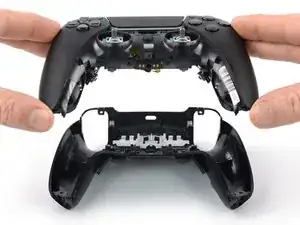
This guide shows how to open the Scuf Reflex controller for repairs.
-
-
Before starting repairs, turn off your device and unplug any cables.
-
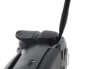
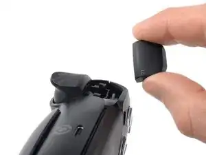
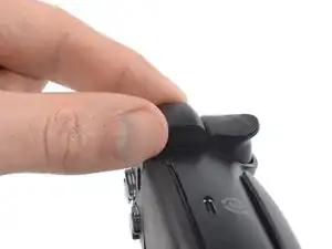
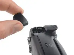
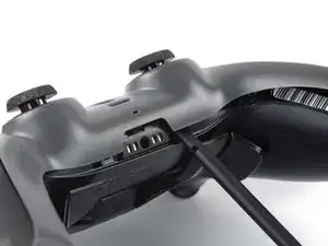
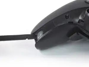
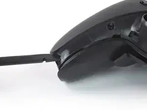
Insert the flat end of a spudger between the faceplate and the R1 bumper.
-
Pry up with the spudger to release the clips securing the bumper.
-
-
-
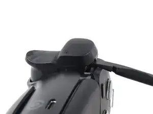
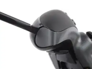
Insert the flat end of a spudger between the faceplate and the L1 bumper.
-
Pry up with the spudger to release the clips securing the bumper.
-
-
-
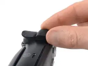
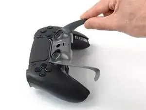
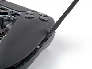
At the bottom tip of the right grip, insert the flat end of a spudger or a clean fingernail between the faceplate trim and the back cover.
-
Pry up to release the faceplate trim’s bottom right clip.
-
-
-
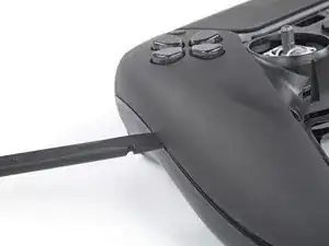
At the bottom tip of the left grip, insert the flat end of a spudger or a clean fingernail between the faceplate trim and the back cover.
-
Pry up to release the faceplate trim’s bottom left clip.
-
-
-
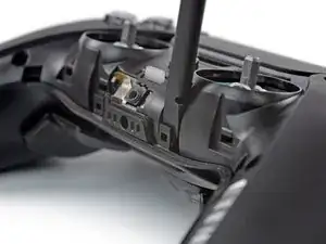
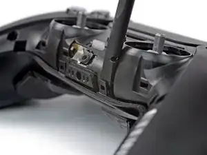
Insert the flat end of a spudger between the faceplate trim and the back cover, next to the headphone jack.
-
Pry up to release the plastic clips securing the center of the faceplate trim.
-
-
-
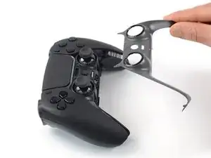
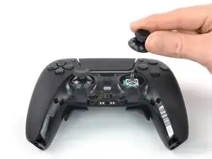
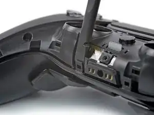
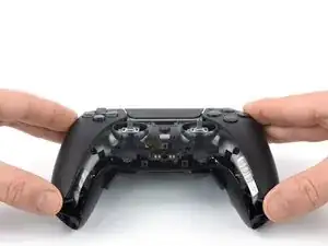
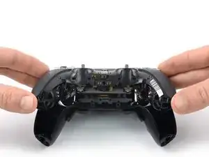
Lift the bottom edge of the faceplate trim and thread it up and over the thumbsticks.
-
Pull the top corners of the faceplate trim out from underneath the faceplate and remove the faceplate trim.
-
-
-
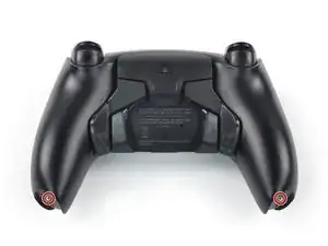
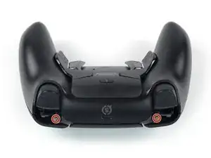
Use a Phillips screwdriver to remove the four 6.5 mm-long screws securing the back cover, two near the triggers and two at the bottoms of the grips.
-
-
-
Insert a spudger underneath the bottom right corner of the faceplate and pry up to release the plastic clip.
-
-
-
Insert a spudger underneath the bottom left corner of the faceplate and pry up to release the plastic clip.
-
-
-
Insert the flat end of a spudger between the plastic clip next to the headphone jack and the faceplate.
-
Pry the plastic clip away from the faceplate to release it.
-
Repeat to release the second clip.
-
-
-
Insert the flat end of a spudger between the right edge of the faceplate and the back cover.
-
Pry down to release the plastic clip securing the faceplate.
-
-
-
Insert the flat end of a spudger between the left edge of the faceplate and the back cover.
-
Pry down to release the plastic clip securing the faceplate.
-
-
-
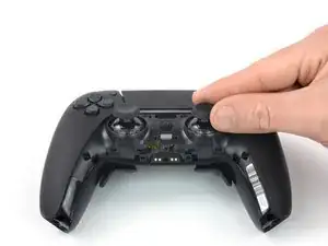
Carefully lift up the bottom of the faceplate assembly.
-
Pull the faceplate assembly down and remove it.
-


To reassemble your device, follow these instructions in reverse order.