Introduction

Is your OnePlus Nord N200 rear cameras failing to take clear photos or not working at all? If so, it might be time to replace the camera component. This guide will walk you through the replacement process step by step on how to replace the cameras in your OnePlus Nord N200, model number DE2118.

This guide is intended to walk you through the necessary steps for replacing the rear camera modules of your device, helping restore full functionality. You’ll need a set of precision tools and a new camera module specifically designed for the OnePlus Nord N200. With these tools in hand, you can restore your phone’s ability to capture photos.

Symptoms that suggest the need for a camera replacement include blurry or distorted photos despite clean lenses, the camera app crashes or fails to open, black screen within the camera app, and error messages related to camera hardware.

For more detailed troubleshooting, please visit our comprehensive troubleshooting page.

Important Tips and Warnings:

Ensure that your OnePlus Nord N200 is powered off before beginning any repair work to avoid short circuits or other damage.

After replacing the camera but before fully reassembling the phone, power on your device to test the new camera’s functionality. This avoids having to disassemble again in case of issues.

It's a good practice to back up your data before starting the repair to protect against potential data loss.

  1. Phh5fVh4ajTFuMdF
    Phh5fVh4ajTFuMdF
    KsCRARKpr12hEnMU
    yRbOyNhYDPYXnEhM
    • Due to its surface, the suction tool won't hold onto the phone's rear glass. A thin slicing tool is required.

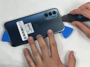
    • Insert the Jimmy into the seam between the rear glass and the midframe at the bottom edge of the phone to create a gap.

    • This may require some force.

    • Leave the Jimmy in place for a few seconds to prevent the adhesive from resealing.

  2. Up4sWcQTTm5jaBCR
    Up4sWcQTTm5jaBCR
    IqlQDuCXs2mVAYvH
    PTFhBFgXwjWXfpyr
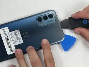
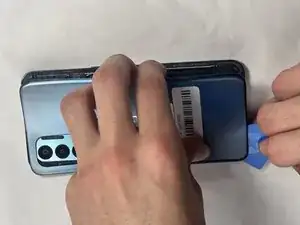
    • Insert an iFixit opening pick into the gap you created with the Jimmy.

    • Slide the Jimmy around the phone to slice the adhesive.

    • Insert a second iFixit opening pick at the spot you have sliced open to keep it open.

  3. GX3EPLvGOJrkSxHV
    GX3EPLvGOJrkSxHV
    6Y5ZXYCnxTMRHxKZ
    jI4FptXtWWECRDKQ
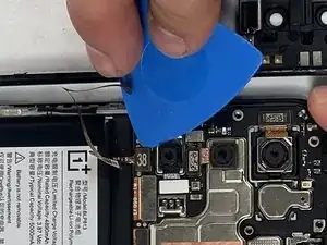
    • Slide the iFixit opening pick along the top edge to slice the adhesive.

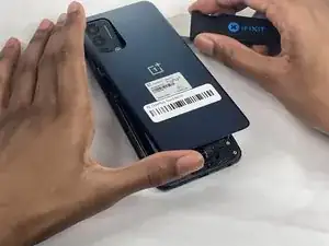
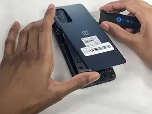
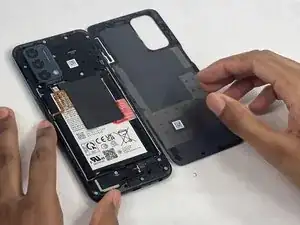
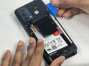
    • Start prying the back plate off the phone.

  4. XGjU2NyFN24TusHT
    XGjU2NyFN24TusHT
    oSgItupTFXasJBvE
    wTktWCgQuhKFARjS
    • Remove the back cover.

  5. WAbV1FhoWgUAm3fn
    WAbV1FhoWgUAm3fn
    qJuR6SRkRtasJCBg
    WreAN6RJVjXXDG5e
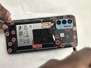
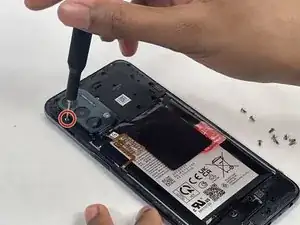
    • Use a Phillips #00 screwdriver to remove the sixteen 3.6 mm-long screws securing the midframe.

    • The orange circle represents a hidden screw that also needs to be screwed out. (At first glance it may not look like a screw).

  6. SQmbVkIEm3nDiEZV
    SQmbVkIEm3nDiEZV
    SHaYKukVPMNnZ1ll
    aWrY5Qguw4TXhOwE
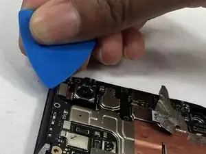
    • Gently insert the Jimmy to create a gap between the midframe and the top of components in the bottom case.

    • Slide an opening pick around the edge of the midframe to slice the adhesive.

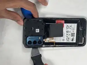
    • Use the Jimmy to pry off the midframe of the phone.

  7. ZLfJTWlHmvTJXKYB
    ZLfJTWlHmvTJXKYB
    fDeSGTpDFVEJIvHQ
    sQAMaCl3CKEINAEu
    • Use your hands to finish prying open the midframe off the phone.

    • Watch out for the fingerprint reader cable when taking off the back tray as it is still connected. If you are not careful, it could be damaged.

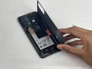
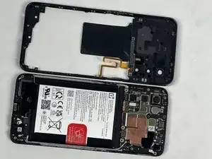
    • Pull the midframe off of the phone and lay it to the side of the phone.

  8. jpIqZWUnyrkIEtri
    jpIqZWUnyrkIEtri
    ITxSHDAWmwvdbfru
    RglMLtv2k43rRQMC
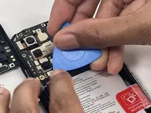
    • Place a spudger or an opening tool under the connector's edge and pry straight up to disconnect the fingerprint cable connector.

    • Move the fingerprint reader cable to the side along with the midframe.

  9. Ib3ZYZeLNbUhfoOk
    • Remove the midframe.

  10. f1dEFCkpMNB2uaZT
    f1dEFCkpMNB2uaZT
    oGugJ5jNcH1LGBZr
    LXb4BxRnHXijZfga
    • Before you start with the repair, make sure to disconnect the battery from the charger to avoid damaging your phone.

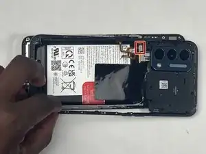
    • Place a spudger or an opening pick under the connector's edge and pry straight up to disconnect the battery.

    • Make sure to pry under the edge of the connector itself, and not under the socket on the board. Otherwise, you risk permanently damaging the socket.

    • Work carefully: don't pry on or accidentally scrape any small, surface mounted components on the board.

    • To reconnect, align the connector carefully over its socket and press down with your fingertip—first on one side, then the other—until it clicks into place. Don't try to force the connector into place. If you're having trouble, reposition it and try again.

    • Don't press down on the middle of wider connectors until they're fully seated. If misaligned, the connector or the pins underneath can bend or break, causing permanent damage.

  11. qKl3neiwryigGHv3
    qKl3neiwryigGHv3
    uVBSybAC1E1enEmV
    txB2yfuY1QwoG2DZ
    • The black Coaxial connector should be disconnected first as it is the ground cable.

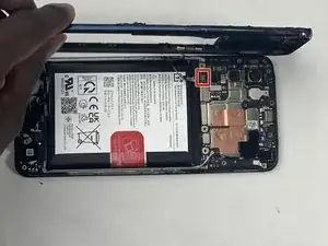
    • Peal the tape up in the upper right corner of the phone to reveal the black coaxial cable.

    • To disconnect the black coaxial cable, slide a thin, ESD-safe pry tool or angled tweezers under the metal neck of the connector (as close to the head as possible) and lift straight up from the board.

    • When working with these connectors, it's key to always lift the head straight up. If pried on at an odd angle, you risk breaking the socket off of the board underneath.

    • Reconnecting these can be tricky. Use tweezers to hold the connector in place over its socket and gently press down with your finger or a spudger—the connector should "snap" into place. If you're having trouble, reposition the head and try again.

    • Don't try to force the connector into place or you may permanently damage it.

  12. uOfsfEJOMvFNWvfV
    uOfsfEJOMvFNWvfV
    KiCKZFCqHLVmvBEV
    RbyHNwVEyCScKW3H
    • Slide a thin, ESD-safe pry tool or angled tweezers under the metal neck of the white coaxial cable connector and lift straight up from the board.

    • Use the tweezers to move the white coaxial connector away from the board.

  13. B1OvPWYuPMGlkcNx
    B1OvPWYuPMGlkcNx
    InAFy6lF12rhNokV
    LXMkBaoaIoyDRFDe
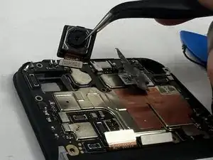
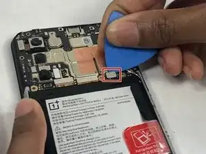
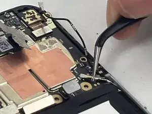
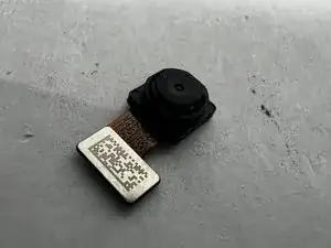
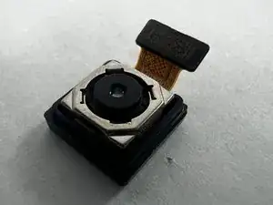
    • Place a spudger or an opening tool under the edge of the small camera's press connector and pry straight up to disconnect it.

    • Make sure to pry under the edge of the connector itself, and not under the socket on the board. Otherwise, you risk permanently damaging the socket.

    • Work carefully: don't pry on or accidentally scrape any small, surface mounted components on the board.

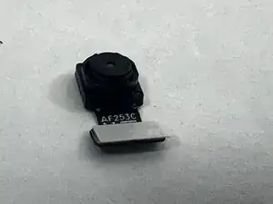
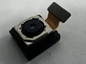
    • Use the tweezers to remove the camera module from the board.

    • To reconnect, align the connector carefully over its socket and press down with your fingertip—first on one side, then the other—until it clicks into place. Don't try to force the connector into place. If you're having trouble, reposition it and try again.

    • Don't press down on the middle of wider connectors until they're fully seated. If misaligned, the connector or the pins underneath can bend or break, causing permanent damage.

    • You don't have to disconnect this specific camera. If you know which camera is faulty you may skip this and go to directly disconnecting the faulty camera.

  14. JdCn6cHKxXheyFLs
    JdCn6cHKxXheyFLs
    SLcntPjI2LRWsjOL
    • Remove the small rear camera.

  15. wWhspDPaGZ5ZMLAY
    wWhspDPaGZ5ZMLAY
    qKfQBIV6RiEnURhB
    IVSNQQ6qDGQStDiw
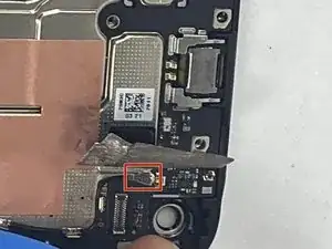
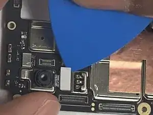
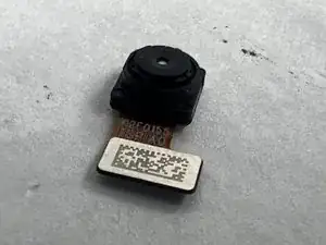
    • Repeat the process to detach the middle camera press connector.

    • Use the tweezers to grab the camera module and move it away from the board.

    • You don't have to disconnect this specific camera. If you know which camera is faulty you may skip this and go to directly disconnecting the faulty camera.

  16. HXlTOKEQOGVkGaAw
    HXlTOKEQOGVkGaAw
    AIWVkDvkdwPMGbmk
    • Remove the middle rear camera.

  17. 4SVcGuQTwtSRMKSS
    4SVcGuQTwtSRMKSS
    wdxBiUNeyhOt3GPm
    XSwJkZNZlmysBx4H
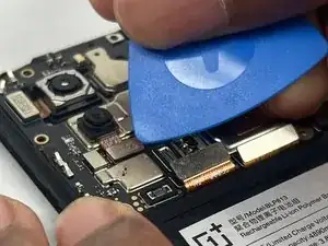
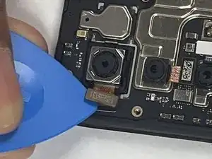
    • Place a spudger or an opening tool under the connector's edge of the third camera and pry straight up to disconnect it.

    • Use the tweezers to grab the camera module and move it away from the board.

    • You don't have to disconnect this specific camera. If you know which camera is faulty you may skip this and go to directly disconnecting the faulty camera.

  18. fiFbGXrdKFjbdEDI
    fiFbGXrdKFjbdEDI
    V2lekBPIhS3qAPeC
    qknkaBv5BoJLNjlJ
    • Remove the larger rear camera.

Conclusion

To reassemble your device, follow these instructions in reverse order.Take your e-waste to an R2 or e-Stewards certified recycler.

Fabrise Niyonkuru

Member since: 18/03/24

1069 Reputation

0 comments