
Introduction
Is your phone experiencing frequent crashes or failing to boot up, suggesting a possible issue with the motherboard? If so, here's your guide to replacing the faulty motherboard and restoring your device's functionality. You'll need a set of precision tools and a replacement motherboard compatible with your phone model.
This guide shows how to replace the motherboard in the OnePlus Nord N200, model number DE2118. This guide will provide you with the essential steps to safely remove and replace the motherboard, the central component that integrates the main functionalities of your device.
Indications that the motherboard may need to be replaced include: Persistent software issues that do not resolve with a factory reset, frequent crashing or rebooting, physical damage to the board, and overheating issues that persist despite cleaning and maintenance.
For more detailed diagnostics, you might consult our troubleshooting page.
Important Tips and Warnings:
Ensure the device is completely powered off before beginning any work to avoid electric shock or damaging the components.
Always back up your data as replacing the motherboard involves removing all memory components, and data could be lost.
-
-
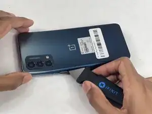
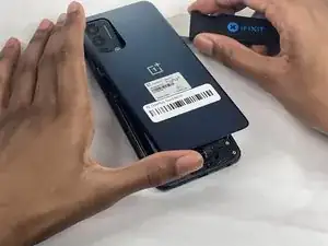
Insert the Jimmy into the seam between the rear glass and the midframe at the bottom edge of the phone to create a gap.
-
-
-
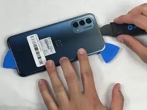
Insert an iFixit opening pick into the gap you created with the Jimmy.
-
Slide the Jimmy around the phone to slice the adhesive.
-
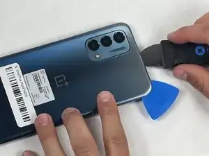
Insert a second iFixit opening pick at the spot you have sliced open to keep it open.
-
-
-
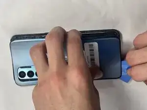
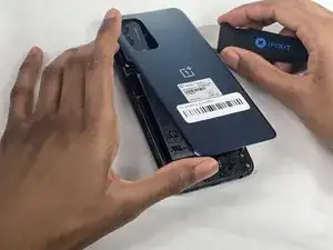
Slide the iFixit opening pick along the top edge to slice the adhesive.
-
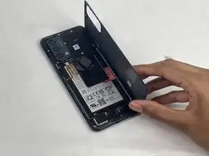
Start prying the back plate off the phone.
-
-
-
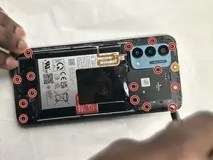
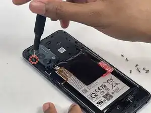
Use a Phillips #00 screwdriver to remove the sixteen 3.6 mm-long screws securing the midframe.
-
-
-
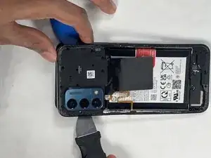
Gently insert the Jimmy to create a gap between the midframe and the top of components in the bottom case.
-
Slide an opening pick around the edge of the midframe to slice the adhesive.
-
Use the Jimmy to pry off the midframe of the phone.
-
-
-
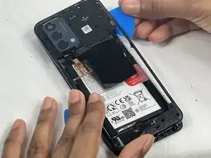
Use your hands to finish prying open the midframe off the phone.
-
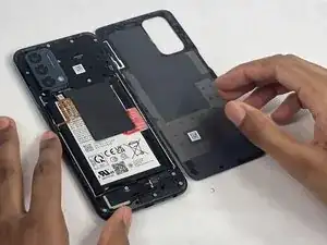
Pull the midframe off of the phone and lay it to the side of the phone.
-
-
-
Place a spudger or an opening tool under the connector's edge and pry straight up to disconnect the fingerprint cable connector.
-
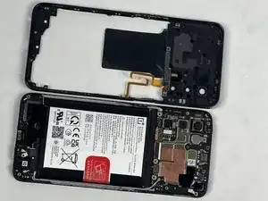
Move the fingerprint reader cable to the side along with the midframe.
-
-
-
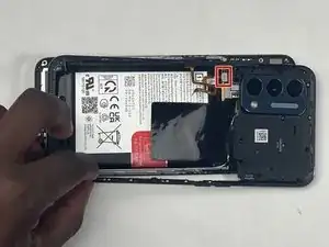
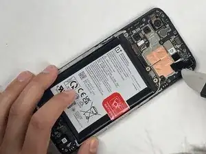
Place a spudger or an opening pick under the connector's edge and pry straight up to disconnect the battery.
-
-
-
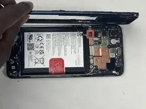
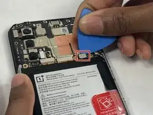
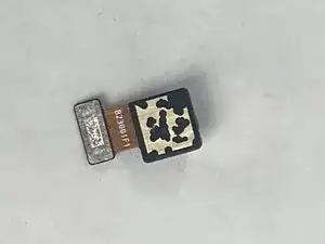
Place a spudger or an opening tool under the connector's edge and pry straight up to disconnect the front-facing camera from the motherboard.
-
-
-
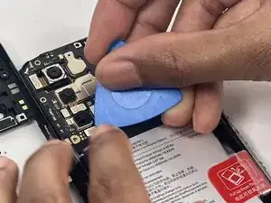
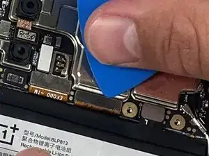
Place an opening pick or a spudger under edge of the two press connectors and pry straight up to disconnect them.
-
-
-
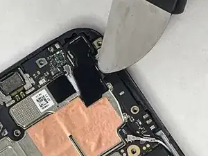
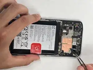
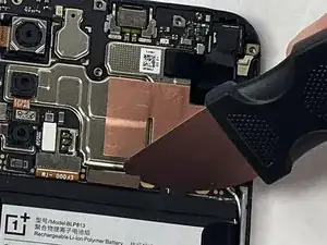
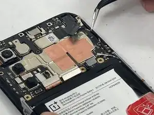
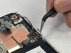
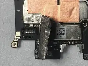
Peal the tape up in the upper right corner of the phone to reveal the black coaxial cable.
-
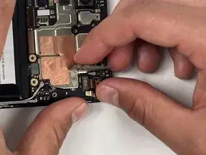
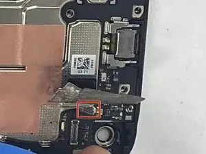
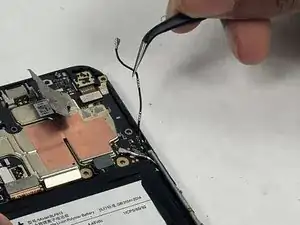
To disconnect the black coaxial cable, slide a thin, ESD-safe pry tool or angled tweezers under the metal neck of the connector (as close to the head as possible) and lift straight up from the board.
-
-
-
Slide a thin, ESD-safe pry tool or angled tweezers under the metal neck of the white coaxial cable connector and lift straight up from the board.
-
Use the tweezers to move the white coaxial connector away from the board.
-
-
-
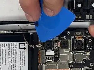
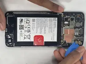
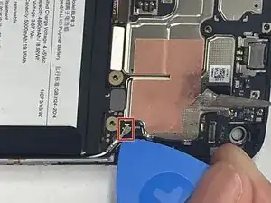
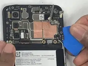
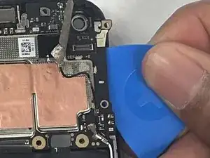
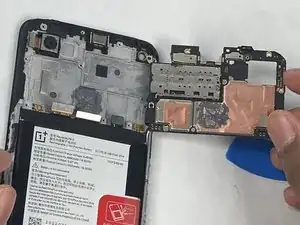
Insert an opening pick or spudger under the gold clip on the top right of the phone to unclip the motherboard.
-
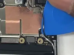
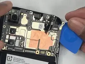
Slide the opening pick under the edge of the motherboard to begin removing it.
-


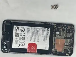


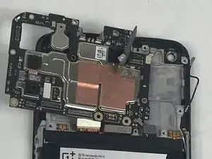
To reassemble your device, follow these instructions in reverse order. Take your e-waste to an R2 or e-Stewards certified recycler.
