Introduction
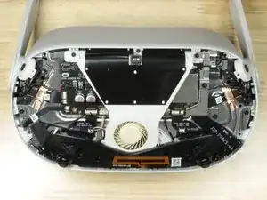
The Oculus Quest 2, also known as the Meta Quest 2, is a VR headset developed by Facebook (formerly Oculus) and is the 2nd iteration of the original Quest. The Quest 2 can run as a standalone headset, or in tandem with a computer when it's connected with either a USB cable or over Wi-Fi. The headset also features a Qualcomm XR2 processor, 6 GB of RAM, and a resolution of 1823 x 1920 per eye.
Also, be sure to keep track of all the screws, this headset has a lot of them.
Consult the Recognizing & Disconnecting Cable Connectors (RDCC) guide for information about the connectors.
For step-by-step repair guides, click here.
-
-
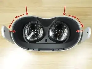
One side at a time, insert a pick next to the nosepiece, slide it to the edge and pry.
-
When both sides are loose, carefully lift the cover out, and fold it so that the nose piece is on the outer perimeter of the device, as shown in the second image.
-
Lift the small black clip on the ZIF connecter up, and pull the flex cable out.
-
-
-
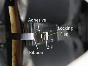
The ribbon cable is lightly attached to the headset with adhesive and the cable is connected with a ZIF connector. Consult Step 1 of the Recognizing & Disconnecting Cable Connectors guide (RDCC guide) for ZIF connector info.
-
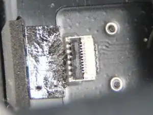
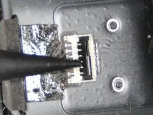
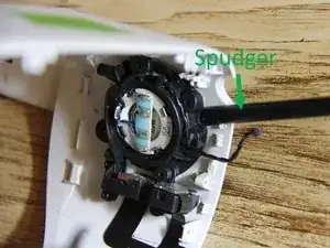
Use the tip of a spudger to flip up the locking flap to release the cable. See pictures 2 and 3 to understand how the flap operates.
-
-
-
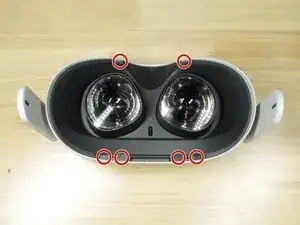
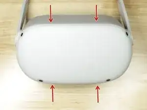
Insert a pick and pry at these four spots to release the clips.
-
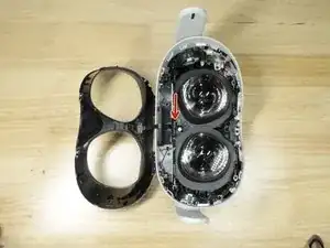
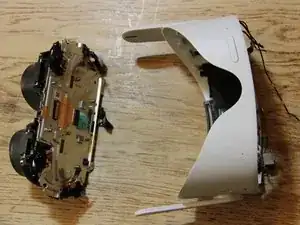
Lift the front cover away from the headset.
-
-
-
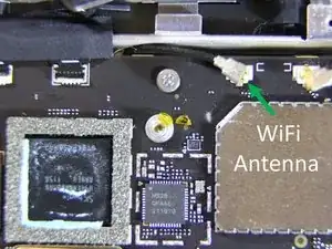
Unplug the side WiFi antenna. See step 5 of the RDCC guide. To disconnect the cable, slide a thin, ESD-safe pry tool or tweezers under the metal neck of the connector and lift straight up from the board.
-
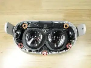
Remove the single 4.4 mm long P0 screw
-
Remove the two 2.3 mm long P0 screws
-
-
-
Unplug the battery. See Step 4 of the RDCC Guide. Use the spudger to pry the connector straight up.
-
Remember to put part of the battery ribbon cable under the logic board when reassembling.
-
-
-
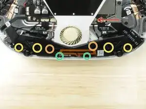
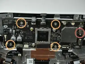
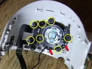
Remove 2x P0, 4.8 mm long screws.
-
Remove 4x P0, 4.8 mm long screws.
-
Remove 2x P0, 10.7 mm long screws.
-
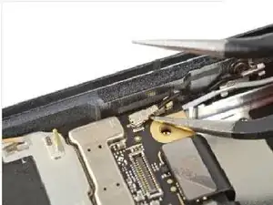
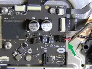
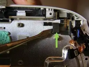
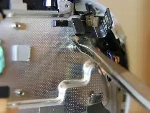
The arrow points to the Bluetooth antenna. To disconnect see step 5 of the Guide. Go to picture 2. To disconnect the cable, slide a thin, ESD-safe pry tool or tweezers under the metal neck of the connector and lift straight up from the board.
-
Picture 3. Remove the antenna from the headset.
-
-
-
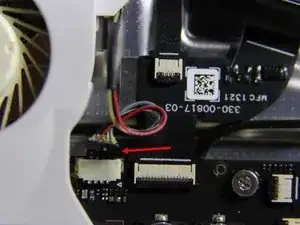
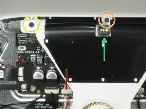
Unplug the fan.
-
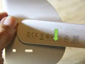
1x T2 screw
-
1x P0 screw
-
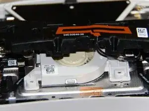
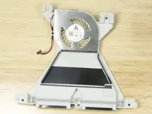
Lift the front LED away from the headset.
-
Lift the fan away from the headset.
-
-
-
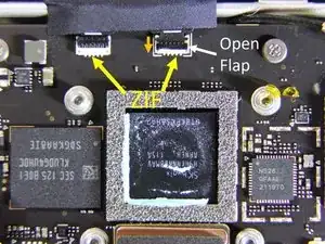
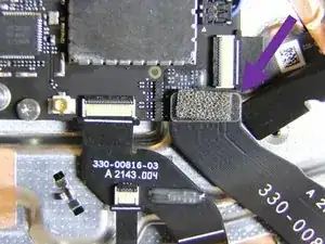
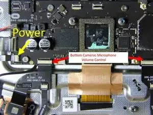
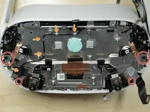
There are 2 ZIF connectors near the top of the mainboard. The ZIF flap on the right has been opened. The ZIF flap is opened by pushing down in the direction of the orange arrow.
-
Unlatch both ZIF connectors and disconnect the cables. These cables lead to the front LED and IPD sensor, and proximity sensor.
-
Unplug the side WiFi antenna connector. See step 5 of the RDCC guide. To disconnect the cable, slide a thin, ESD-safe pry tool or tweezers under the metal neck of the connector and lift straight up from the board.
-
Unplug the cable leading to the USB Type-C port and headphone jack. See Step 4 of the RDCC Guide. Use the spudger to pry the press connector straight up.
-
-
-
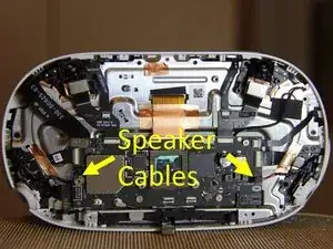
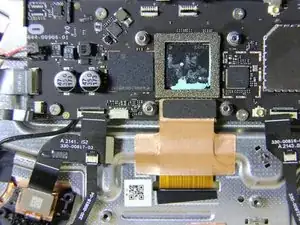
Two sets of speaker cables are connected to the main board.
-
Grab the wires and pull out to disconnect the speaker cables.
-
-
-
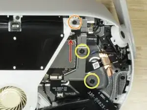
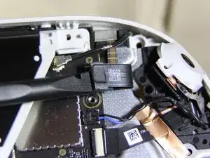
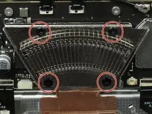
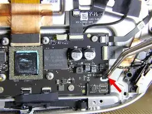
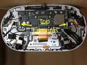
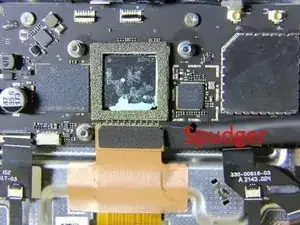
Disconnect the ZIF connectors for the top cameras
-
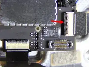
The ZIF connector is shown in the second picture. A spudger should be used to push up the locking flap as shown by the red arrow.
-
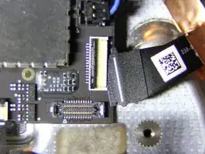
When the flap is open the ribbon cable may be pulled from the connector.
-
-
-
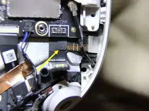
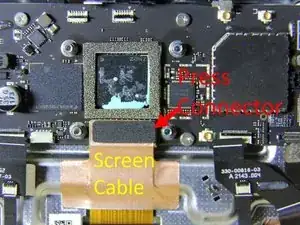
The screen cable is attached with a press connector.
-
Use the spudger to pry the press connector straight up. See Step 4 of the RDCC Guide.
-
-
-
Remove the 4 P0 screws
-
Unroute the side WiFi antenna.
-
The battery power comes to the midframe through this cable. The cable has a metal pad on the bottom and is attached to the midframe with glue. Separate the metal plate on the bottom of the connector from the midframe.
-
-
-
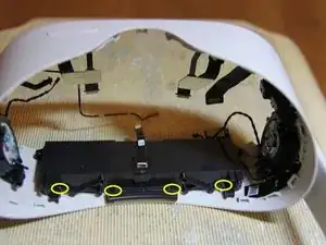
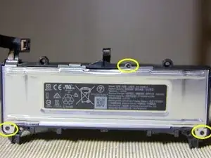
2 x P0 hold the battery to the front of the case.
-
4 x P0 hold the battery to the back of the case.
-
-
-
Release the speaker wire from the speaker retainer.
-
Remove the seven P0 screws from the speaker retainer and USB port.
-
Use the spudger to free the speaker retainer.
-
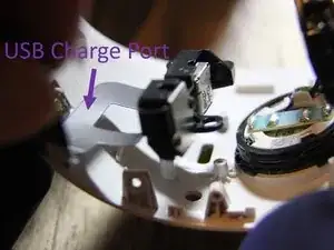
Remove the USB charge port and the speaker retainer.
-
-
-
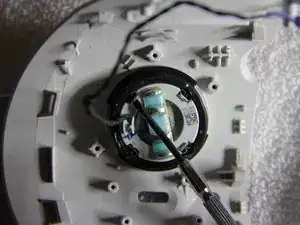
Use a small screwdriver to tip up the tabs on the springs.
-
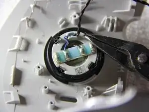
Remove the springs using needle nose pliers.
-
-
-
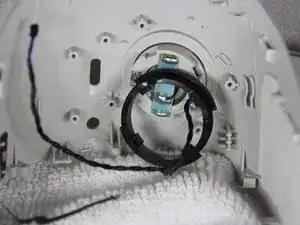
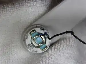
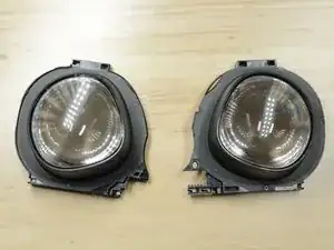
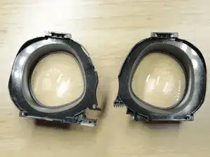
The arm and speaker are passed through the headset and locked in place with the rubber retaining ring.
-
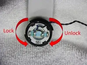
Tabs in the rubber retaining ring pass through the slots in the arm. These are the slots that previously held the springs. the ring is turned to lock or unlock the arm.
-
-
-
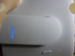
When you are working on the arm located near the on/off button, you must put your hand through the part of the headset that is normally towards your face to grasp the retaining ring. You then push the arm down in the direction shown in the second picture.
-
When working on the arm located near the USB port you must put your hand through the front of the headset to grasp the retaining ring. You then push the arm down as shown in the third picture.
-
-
-
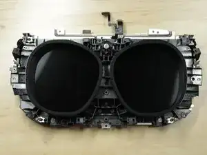
Small metal tabs hold the guide rails that the lenses slide on. Removing the rails reveals the display.
-

83 comments
Thank you so much to me for making this guide. Helped me a lot!
It is worth emphasizing that this device has 2! WIFI antennas.
Anyone who wants to disconnect WIFI from their device must disconnect both.
Their connection to the motherboard, is right next to each other, but the right connection is immediately revealed while the left connection next to it is hidden under the black cover and requires a number of additional disassembly steps.
Alternatively, anyone who wants to disconnect WIFI from their device can disconnect the wires in the area where they connect to the antenna stickers on the right and left sides of the eyepieces of the glasses, thus saving all the disassembly of the front cover.
Thanks!! this really helped me, I have already customized mine with an official custom filter, but this will add an additional layer of Kashrus.
If you just need to replace a camera… it’s 14 screws. You need a T2 and a PH0 (not a P0…) Pretty easy once you get the front cover off and not covered here. It’s pretty easy to see what you do once you get in there though. Good luck!
PH0 and P0 are the same :)
Lylo -
Bravo pour ces informations. Un grand merci
It’s actually 6x T3 screws. A T2 driver is smaller than the groves of the T3 screws, will slip and strip.
Steven -
It may depend on your bit manufacturer. I used an ifixit T2.
Daniel Yoder -
What screw size are these? I need to replace one but I don't know what to search for
Michele Bright -
I have T2 on mine as well
weiwei.e.sun -
What if one of the screws strips? We are using a t3 and it got all screws out but one. Now we cannot get that last screw out
AliD -
Not much you can do except drill it out.
Kmic -