
Introduction
Use this guide to replace a broken screen on your Nokia G22.
This guide is written for the genuine Nokia G22 screen assembly. The assembly consists of the screen and midframe together as one part. Make sure you have the right part before you begin this repair.
Note: This procedure requires you to transfer all of your phone's internals to the new screen assembly.
For your safety, discharge the battery below 25% before disassembling your phone. This reduces the risk of fire if the battery is accidentally damaged during the repair. If your battery is swollen, take appropriate precautions.
-
-
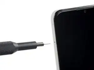
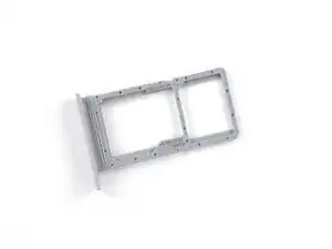
Insert a SIM eject tool, bit, or a straightened paper clip into the small hole on the SIM card tray on the upper left edge of the phone.
-
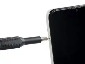
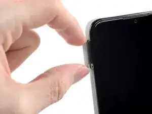
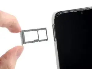
Press firmly to eject the tray.
-
-
-
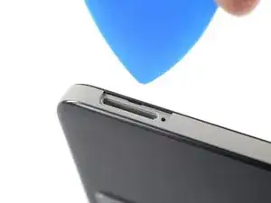
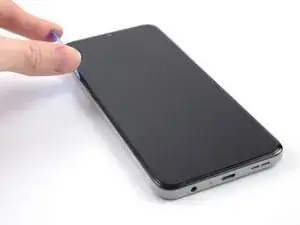
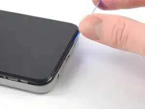
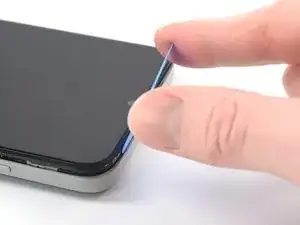
Position the opening pick at a steep downward angle between the back cover and the screen assembly.
-
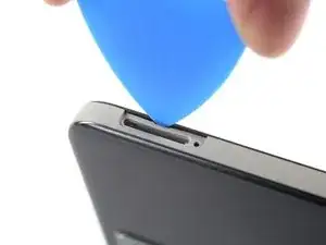
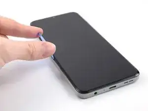
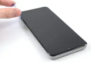
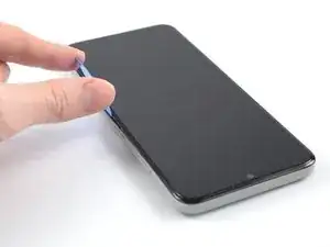
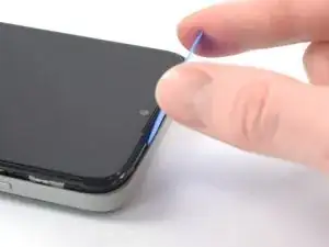
Slide the opening pick down the left edge of the phone to release the plastic clips.
-
-
-
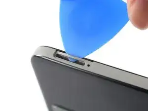
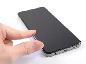
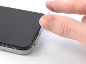
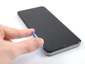
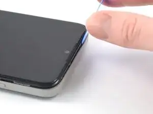
Turn the opening pick around the corner and continue to slide it along the bottom edge to release the plastic clips.
-
-
-
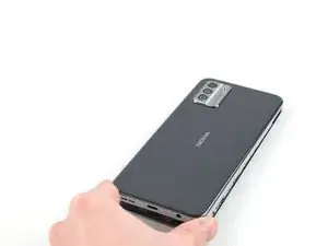
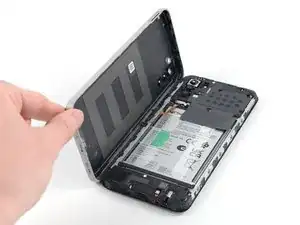
With the phone laying screen-side down, carefully lift the right edge of the back cover, opening it like a book.
-
Lay the back cover next to the phone.
-
-
-
Use a Phillips screwdriver to remove the 3.8 mm‑long screw securing the fingerprint reader bracket.
-
-
-
Use the flat end of a spudger to disconnect the fingerprint reader by prying the connector straight up from its socket.
-
Remove the back cover.
-
-
-
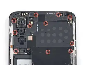
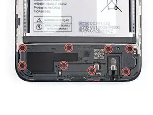
Use a Phillips screwdriver to remove the eleven 3.8 mm-long screws securing the motherboard cover.
-
-
-
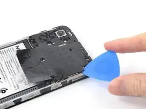
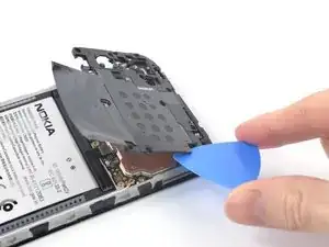
Insert an opening pick under the right edge of the motherboard cover to release its plastic clips.
-
Flip the motherboard cover over the top edge of the phone.
-
-
-
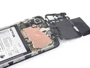
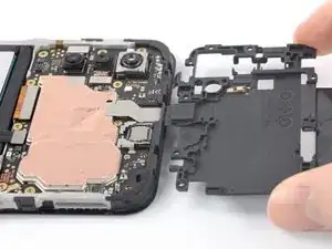
The motherboard cover has two short adhesive tapes wrapped around the top edge and onto the frame.
-
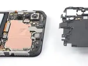
Pull the motherboard cover away from the frame to separate the adhesive tape and remove it.
-
-
-
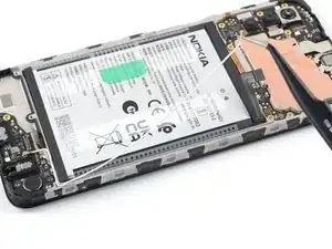
Use the flat end of a spudger to disconnect the battery cable by prying the connector straight up from its socket.
-
-
-
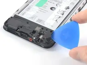
Insert an opening pick underneath the right edge of the loudspeaker.
-
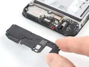
Twist the opening pick to release loudspeaker from the plastic clips holding it in place.
-
-
-
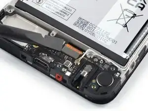
Use the flat end of a spudger to disconnect the display cable by prying the connector straight up from its socket.
-
-
-
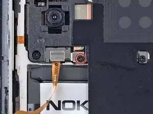
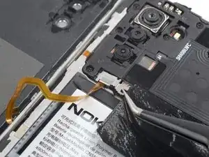
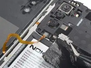
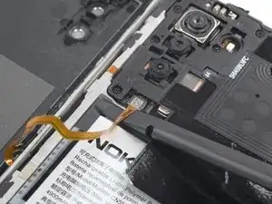
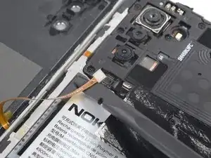
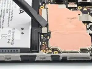
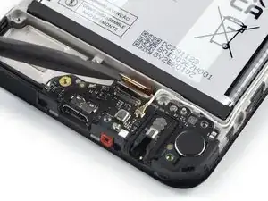
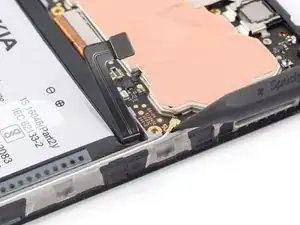
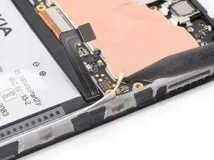
Use the pointed end of a spudger to disconnect the antenna cable by prying the connector straight up from its socket on the motherboard.
-
-
-
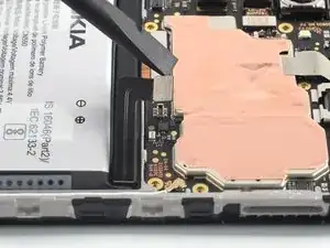
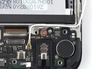
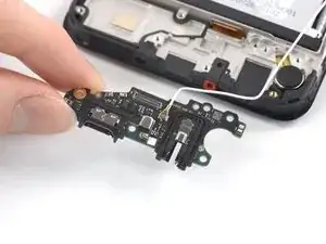
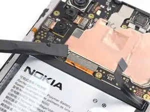
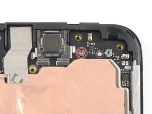
Use a Phillips screwdriver to remove the 2.8 mm‑long screw securing the charging port assembly.
-
-
-
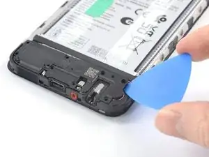
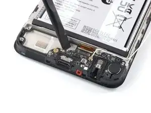
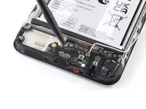
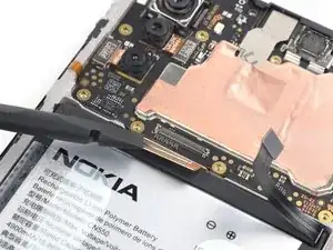
Insert the flat end of a spudger underneath the top edge of the charging port assembly.
-
Pry up the charging port assembly by twisting the spudger until you can grip it with your fingers.
-
-
-
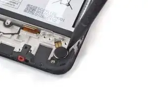
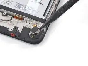
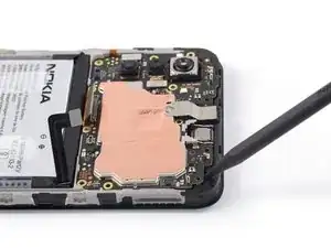
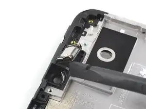
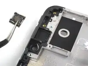
Insert the pointed end of a spudger into the small recess on the upper right side of the vibration motor.
-
Pivot the spudger up to pry up the vibration motor off of the adhesive securing it underneath.
-
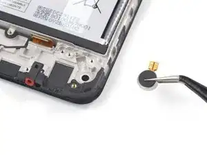
Use a pair of tweezers or your fingers to remove the vibration motor.
-
-
-
Use the flat end of a spudger to disconnect the display cable by prying the connector up from its socket.
-
-
-
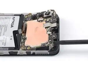
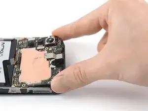
Insert the pointed end of a spudger underneath the top right corner of the motherboard.
-
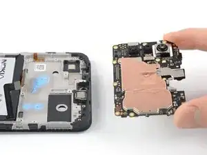
Pry the motherboard up until you can grip it with your fingers.
-
-
-
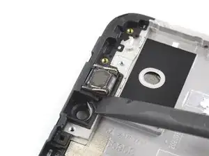
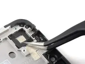
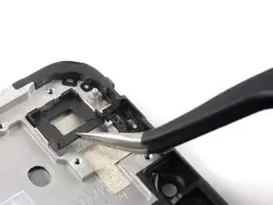
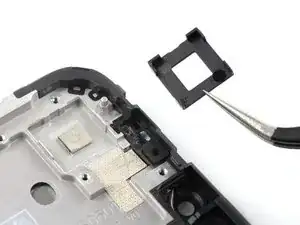
Insert the flat end of a spudger underneath the bottom left corner of the earpiece speaker and pry it out of its recess.
-
Remove the earpiece speaker.
-
-
-
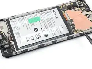
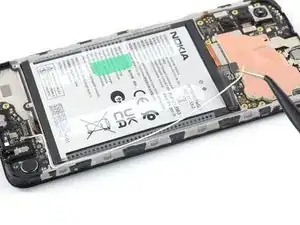
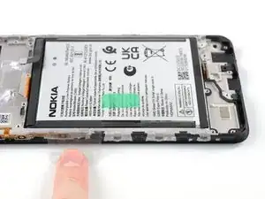
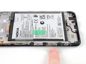
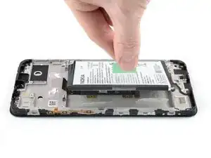
Use your fingers to peel the center green pull tab off of the battery.
-
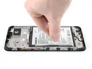
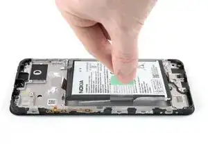
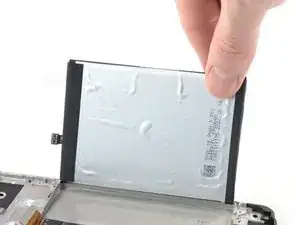
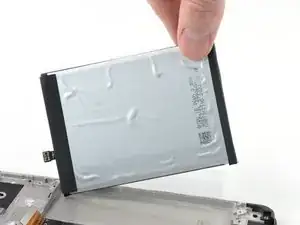
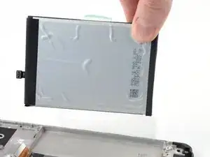
Using one hand to hold the phone down, use your other hand to slowly and steadily lift the center green pull tab up to separate the adhesive securing the battery underneath.
-
If you have any difficulties with stubborn battery adhesive, you can contact "Nokia phones support".
-
-
-
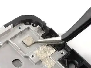
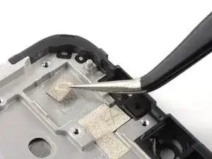
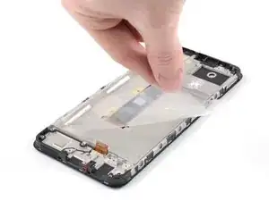
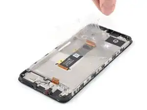
Grab the bottom right edge of the leftover adhesive film and pull it towards the top of the phone with steady force to remove it.
-
Remove the battery adhesive film from its liners and apply it to the battery.
-
Align the bottom edge of the battery (the edge without adhesive) with the bottom edge of the recess.
-
Lower the battery with its film down and press firmly to secure it in place.
-
-
-
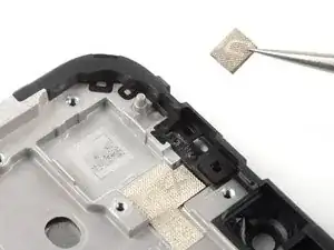
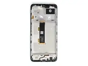
Only the screen assembly remains.
-
If your part comes with battery adhesive pre-installed, remove its plastic liners before continuing to the previous step.
-
If your part has no battery adhesive, remove the clear liner on the pre-cut battery adhesive and apply the sticky section to the battery well. Remove the opaque liner before continuing to the previous step.
-


To reassemble your device, follow these instructions in reverse order.
Take your e-waste to an R2 or e-Stewards certified recycler.
Repair didn’t go as planned? Try some basic troubleshooting, or ask our Answers community for help.

11 comments
Vous marquez "Il est possible de remplacer uniquement l'écran, mais cela nécessite une procédure différente". Pouvez-vous svp me donner le lien pour changer juste l'écran ?
Merci !
Bonjour Emilie,
Nous ne proposons malheureusement pas de guide pour le changement d'écran seul. La procédure est plus complexe et potentiellement plus risquée car la séparation du châssis et de l'écran nécessite une certaine dextérité. Il y a toujours plusieurs possibilités de réparation mais nous recommandons plutôt d'opter pour cet écran complet fournit par Nokia, et donc de suivre les instructions du tuto ci-dessus.
Bonne journée,
Sandra
Bonjour,
Les étapes 30 et 31 ne sont pas nécessaire, l'écran neuf est livré avec la connectique neuve.
Les étapes 33 et 34 ne sont pas nécessaire, le support caméra et la mousse sont fournis neuf avec le kit et l'autocollant neuf.
Idem étape 38, le film plastique est fournis dans le kit, il faut mettre le film neuf sur l'écran avant de replacer la batterie.
Sinon, super tutoriel, le remplacement se fait sans soucis avec le kit d'outillage.
Bonjour Antoine,
Merci de votre remarque ! Même si ces étapes ne sont effectivement pas indispensables comme vous l'avez souligné, nous avons préféré les conserver afin d'être le plus précis possible et pour que les utilisateurs n'oublient pas d'installer ces pièces lors du remontage !
À bientôt,
Sandra