Introduction
If your Nintendo GameCube has stopped working, as in it is no longer able to read your discs, then use this guide to replace the Nintendo GameCube Optical Laser Lens.
Before beginning, make sure to power off your GameCube completely and disconnect from any external power source.
-
-
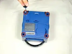
Turn over the Gamecube so that the bottom side is facing up.
-
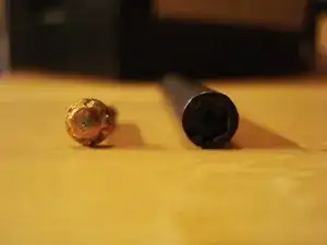
Use the 4.5 mm Gamebit screwdriver to remove all four screws.
-
-
-
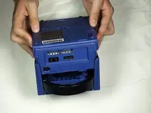
With the bottom side of the GameCube facing upward and the screws removed, carefully pull the outer shell of the unit away from the top half.
-
Move the GameCube so that the inside is facing upwards.
-
-
-
Gently press down on the clips located on either side of the back panel.
-
Carefully remove the back panel from the GameCube.
-
-
-
Use a Phillips #2 screwdriver to remove the two screws on the back of the control port.
-
Carefully separate the gray outer casing of the control port and the circuit board.
-
-
-
The left side of the unit contains the cooling fan and its housing.
-
Carefully remove the two screws attaching the cooling fan housing to the unit.
-
-
-
Remove the four Phillips #1 screws retaining the ground springs.
-
Carefully remove the ground springs from the main unit.
-
-
-
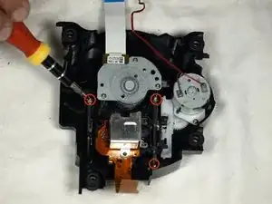
The optical drive is secured to a metal plate.
-
Using a Phillips #2 screwdriver, unscrew the twelve screws that are around the outer edge of the optical drive.
-
-
-
Carefully separate the optical drive assembly from the rest of the GameCube unit.
-
The optical drive assembly is secured to the motherboard underneath by a slot; some force may be required to carefully free the assembly.
-
The metal plate and the actual optical drive will remain attached.
-
-
-
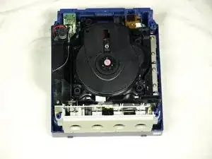
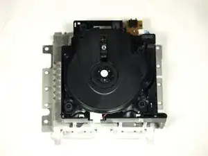
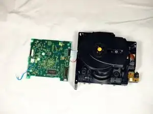
At this point, your optical drive assembly should be separated from your GameCube.
-
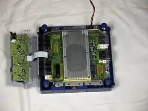
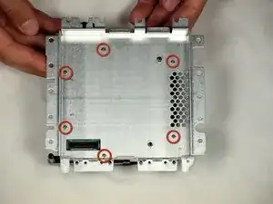
Flip the optical drive assembly upside down.
-
Remove the six screws with a Phillips #1 screwdriver.
-
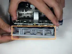
Gently lift and remove the metal plate.
-
-
-
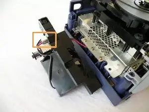
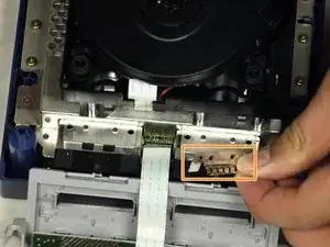
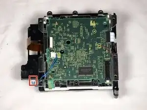
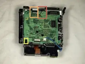
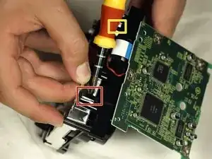
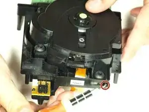
Remove the blue wire by gently pulling.
-
Disconnect the brown cable. This is done by gently pulling the black tab away from the white plastic. This will loosen the tension on the brown cable, allowing it to slide away from the tab gently.
-
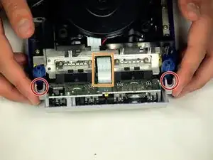
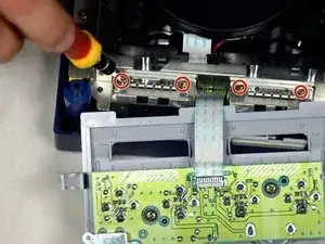
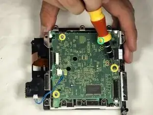
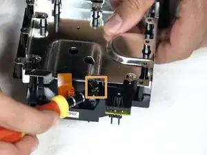
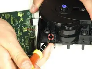
Remove the four Phillips #1 screws connecting the circuit board to the optical drive assembly.
-
The fourth screw is located behind the screwdriver in the third picture.
-
-
-
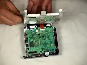
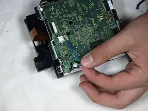
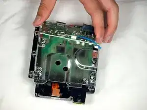
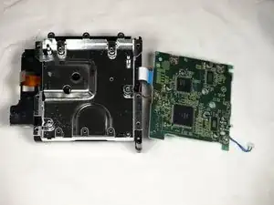
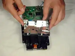
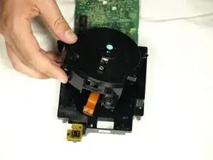
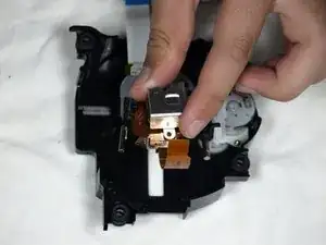
Release the small clip holding the board down.
-
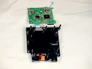
Gently remove the circuit board (the large green square) as shown in the three pictures.
-
Red Wire
-
White ribbon Cable
-
-
-
Use a flathead screwdriver to carefully release the four plastic clips holding the drive assembly together.
-
Carefully use a screwdriver as leverage to unscrew and release the last clip.
-
-
-
Gently lift the metal plate off the drive assembly.
-
Then, flip the two halves of the drive assembly upside down.
-
-
-
Use a flathead screwdriver to release the two clips located on the back half of the drive assembly.
-
The final clip doesn't need to be released; the top half of the drive assembly will slide away from the lower half.
-
Finish removing the top half of the drive assembly from the base.
-
-
-
Once the top half of the drive assembly is detached, turn it upside down.
-
Using a Phillips #1 screwdriver, carefully remove the three final screws near the lens assembly bars.
-
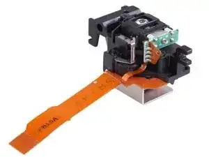
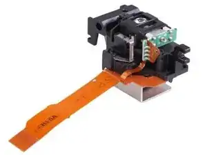
Extract the final three screws and remove the lens assembly.
-
-
-
Once the laser lens is carefully separated from the optical drive assembly, insert the new laser into the optical drive assembly and follow these steps in reverse order for reassembly.
-


To reassemble your device, follow these instructions in reverse order.
