Introduction

This guide has been updated by iFixit staff! Read the new, official guide here.

This guide will help you replace a broken touch sensor or bottom LCD on your DSi. Follow this guide if the system does not respond to input on the touch screen, or if the lower screen becomes cracked. You will need a new bottom LCD and/or touch screen sensor.

  1. g6dlRVZpjEeBlDqS
    • Loosen the two screws on the battery panel. Then lift the panel up to remove it.

  2. ZKKCp1kR1lAijwch
    • L Button.

    • Top of the battery pack.

    • To remove the battery pack, place your fingernail or a spudger at the top of the battery near the L button. Gently lift the battery out.

    That's great. WHAT ABOUT THE THREE OTHER SCREWS KEEPING THE BACK ON!?

    tekgeekster -

  3. ZElvjs4G5DRnVKEX
    ZElvjs4G5DRnVKEX
    NNd3fYSswNeKCoBU
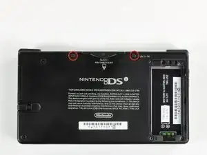
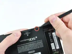
    • Two screws are hidden underneath two rubber feet highlighted in red.

    • Use the tip of a spudger to pry the rubber feet out of the lower case.

    • Depending on the age of your device, the rubber feet may crumble apart as you pry them out. If so, use a fine-tipped tool to scrape out any stuck pieces of rubber.

    One of the feet did break on me, tweezers came in handy for picking it out

    Willie Narvaez -

    I unfolded and sharpened a paperclip. You can use that to stab and hook the rubber without tearing it, as the rubber is thick enough to reseal when reinserted.

    Keegan Andersen -

    Nasty, broke my spudger and the feet in this step.

    TimedIn -

  4. MPpnnO22qoYDH1YH
    • Remove the following screws securing the lower case to the body of the DSi:

    • Six 5.2 mm Phillips #00 screws.

    • One 2.7 mm Phillips #00 screw.

    Impossible d'enlever les vises… trop serré! comment faire?

    evrobert03 -

    i can't get the screw by the gamecard slot out, PH#00 is too small and PH#0 is too big

    Iblowup -

    same problem here. maybe try a JIS?

    darth mango -

  5. MqTKErbDcomH6eMJ
    MqTKErbDcomH6eMJ
    HuePUMK6TciCQZEj
    OkwvvvtBbd53ugBG
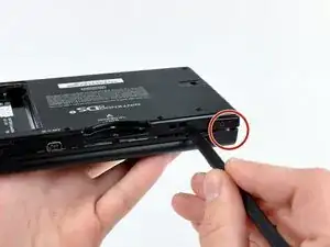
    • Insert the spudger in between the lower casing and lower panel near the top right corner of the DSi.

    • Carefully run the spudger along the edge of the outer casing, creating an opening between the body and the casing.

    • Continue running the spudger around the body of the DSi until the majority of the lower case has been separated.

  6. ZsX1F2YxXpOFEtuH
    ZsX1F2YxXpOFEtuH
    BS25HSFVrSclu2X1
    • Carefully lift the lower casing from its bottom edge.

    • The lower case is still attached to the motherboard by the volume and SD board cable highlighted in red. Do not try to completely remove the lower case of the DSi yet.

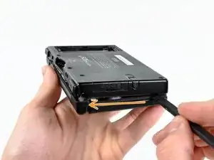
    • Pry the volume and SD board cable up from its socket on the motherboard using a spudger.

    • Once the cable is completely removed, then you may take off the entire outer casing.

    Any help removing the ribbon cable, I have absolutely no clue how to remove this.

    John Brodie -

  7. kmVh26fubSE4TiMD
    • Pull the Wi-Fi board away from the motherboard by its edge closest to the headphone jack.

  8. QDhsgwruDwxGZhwa
    • Pry the Wi-Fi antenna connector straight up from its socket on the Wi-Fi board.

    After reassembling it, I switched my Nintendo DSi xl On and only the blue power light, is on after that it doesn't respond any more, except while charging it blinks

    Phillips -

  9. 2hFHQUOkvfPbdJvR
    • Flip up the black latch and disconnect the D-Pad/Power Button ribbon cable.

  10. dWEpZmQDsygLDOZ1
    dWEpZmQDsygLDOZ1
    OoMrHJOHvhlOBuXt
    QuRDPRr2GOeRAOWs
    • The power connector (with red and black wires) is difficult to remove without damaging it, unless you take a moment and understand how it works. Look at all of the photos for this step before continuing.

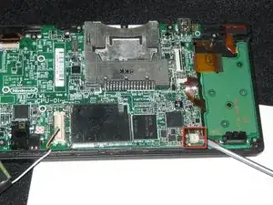
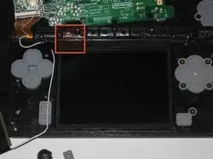
    • The connector is two pieces -- a white "male" piece (connected to the wires), and a beige "female" part (soldered to the main board).

    • There is a small "notch" in the female part, to give you a place to insert a small flat-head screwdriver. Put the corner of your screwdriver in there, and twist it gently to push the white part up (away from the main board). Do not try to pull it to the right (towards the battery board).

    • If it does not lift easily, try again with a smaller screwdriver. You might be pulling the female connector off the board, which will be difficult to repair.

  11. ZrIorgB5yi6QTQ1f
    ZrIorgB5yi6QTQ1f
    RkOnSVoRuGgH1s3N
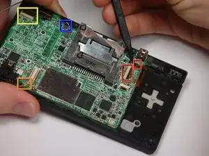
    • If you have not already done so, disconnect the two bottom-LCD ribbon cables from the main board by prying up the black latches and pulling the cable out to the side.

    • The ribbon cable (marked in blue) for the touch screen is particularly thin and fragile; be careful to avoid bending it more than necessary.

    • Flip up the latch and remove the touch screen cable.

    • Flip up the latch and remove the top-screen ribbon cable.

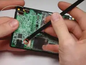
    • Pry up on the orange cable to disconnect it from the main board, much like the antenna cable on the Wi-Fi module.

    • Do not pull on the orange cable that connects to the bottom of the motherboard.

  12. HXOvwVlCv1OUYCK1
    HXOvwVlCv1OUYCK1
    NmbpRL3QlNZruLc2
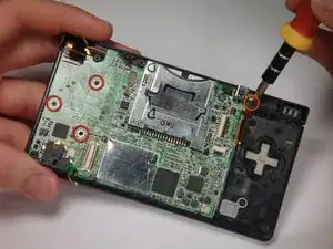
    • Remove 4 Phillips screws from the board.

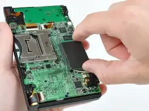
    • Lift the main board from the bottom end and flip it over to reveal the last connector.

    • Keep the main board fairly close to the case, making sure not to damage the last ribbon cable holding it in place.

  13. eOTwPmfiw4DM6LPi
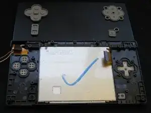
    • Reach under the front of the device, and push the bottom screen towards you, out of the frame.

  14. vUq4FwFdCYjElOIJ
    • If you are replacing the LCD, make a mark on the back of the bad LCD so you know which one is the good one; it is easy to confuse them and you can't test them without reassembling most of the unit.

  15. ENwVwUZTSjFUYMdK
    ENwVwUZTSjFUYMdK
    vwdwOTStCF6um2tT
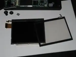
    • The bottom LCD assembly is actually two pieces which are glued together; if you replace one, you need to keep the working part and use it with the new part.

    • Carefully separate the two pieces by inserting a spudger into the groove between the metal piece and the darker piece, then pry them apart.

    • Set aside the broken piece; you should now have one working touch screen and one working bottom LCD, as two separate pieces.

  16. AeDKRlRlhUCJeUkX
    • It is important that the touch screen and LCD sit perfectly flat in the frame, or else you will not be able to close up the device. Putting the touch screen in the frame first helps accomplish this goal.

    • Lay the working touch screen down into the frame from the back side, with the ribbon cable oriented as shown.

  17. QEevLCIThLdXmnHb
    • Place the LCD on top of the touch screen, with the two ribbon cables pointing towards the battery board (as shown in the picture).

    • Make sure that the edge of the LCD is flush with the black plastic frame, or you will not be able to reassemble the unit.

    • Make sure that both the white and pink cables are tucked into the "groove" formed by small plastic pegs; they must not overlap the screw threads or the buttons, or you may damage them while reassembling the device.

Conclusion

To reassemble your device, follow these instructions in reverse order.

bushing

Member since: 24/04/10

10353 Reputation

0 comments