Introduction

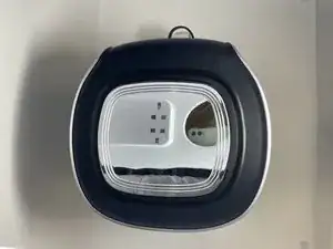
This guide is helpful for replacing the Ninja AF161 Max XL outer gray frame. These steps may be used to remove additional parts from the air fryer.

  1. AHITOWTAgAAmI5JH
    • The back vent cover is directly above where the power cord protrudes.

  2. qTnFNgbn5nbi5WfB
    qTnFNgbn5nbi5WfB
    wJlVciBFaG5wD5hc
    • Use a Phillips #2 screwdriver to unscrew and remove four 1 cm screws from the panel.

  3. PVQw1gfiHrHoYPA1
    PVQw1gfiHrHoYPA1
    TVQEXHvnLnMLXFPe
    • Once unscrewed, remove all four screws in order to remove the back vent cover.

  4. utS2pPdCvQjf1grS
    utS2pPdCvQjf1grS
    MdE4DQDNd5EjaAYN
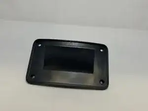
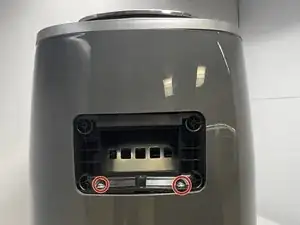
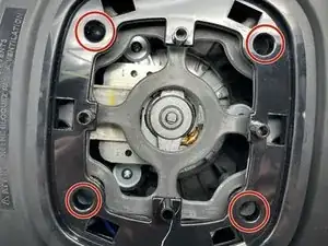
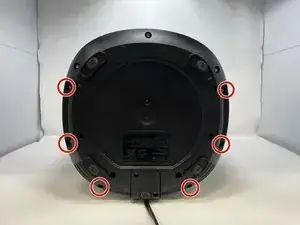
    • After you have the vent removed, you will see two 2.2 cm screws holding the casing in. Use a Phillips #1 screwdriver to remove the two screws.

    • Be wary that the two screws are quite tight and will require a bit of torsion to get out.

  5. CKe3a3UpMSZE2cSF
    CKe3a3UpMSZE2cSF
    Qo2iDFIOBtsQqRn6
    iUqpBRFQ1JOYUCnv
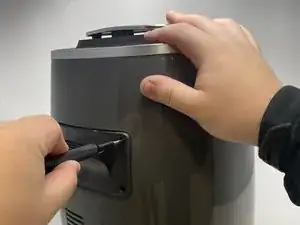
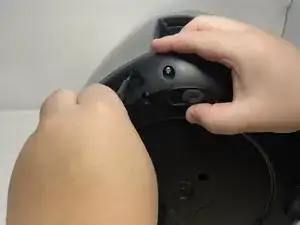
    • Use the a plastic opening tool or a similar object to wedge between the silver top and black rim.

    • Pry all four sides towards the middle with a plastic opening tool to release the tabs.

    • The tabs on the top will make sounds while being detached from the device.

  6. nWKdOot2xAnSDiJw
    nWKdOot2xAnSDiJw
    jWeCNXCYp1yRimnV
    • Unscrew the four 2.2 cm screws with a Phillips #1 screwdriver.

  7. wvyNEddFbSwKUl2U
    wvyNEddFbSwKUl2U
    PiXXlHErSbWbArd5
    • Lay the air fryer on its side.

  8. QZYfAZ6YJYsDxXZj
    QZYfAZ6YJYsDxXZj
    sbAFg551sVpMCqLf
    • Remove six 1.4 cm screws with the TR15 Torx Security Screwdriver.

  9. PUQR6d3V3OGRPRDg
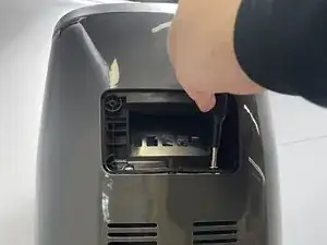
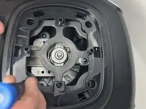
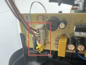
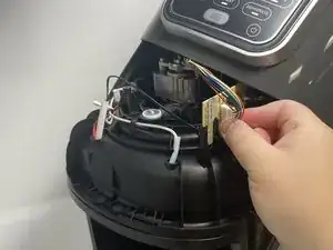
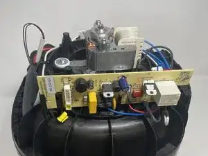
    • Keep the device on its side, and unscrew and remove two 1.4 cm screws with a Phillips #1 screwdriver.

  10. BYv3gYuEB1VyMWIM
    • The lid can now be lifted off. Remove by prying the bottom apart and lifting.

    • After lifting the lid, you will see the white and yellow wire heads that connect the air fryer display screen to the motherboard.

  11. fJjdsQ1XUHXqe5Bi
    fJjdsQ1XUHXqe5Bi
    6CVugOP6EMNtNpEJ
    IY5G4W466NZQHwqJ
    • Pinch the white tab and wire head together and pull to release the connector.

    • Take care to not bend the circuit board while attempting removal of this connector. This will damage the circuit board.

Conclusion

To reassemble your device, follow these instructions in reverse order.

Alina Sanchez

Member since: 14/02/23

342 Reputation

0 comments