Introduction

This guide shows how to remove the motherboard and earpiece speaker in your HMD Pulse smartphone.

  1. yjiVglEySYXSEEUH
    • Let your phone's battery drain below 25% before starting this repair. A charged lithium‑ion battery may catch fire if damaged.

    • Unplug all cables from your phone and completely power it down.

  2. VQ2XTFSdWPyxIYSH
    VQ2XTFSdWPyxIYSH
    KcSRFYDyNIOA24EH
    MYPTW4SmTkBVLaip
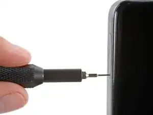
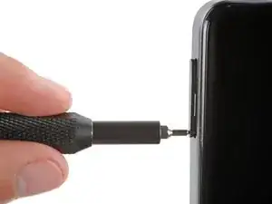
    • Firmly press a SIM eject tool, bit, or straightened paper clip into the SIM card tray hole on the left edge of your phone until the tray ejects.

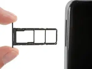
    • Remove the SIM card tray.

    • During reassembly, use the tray's markings to orient and reinsert it properly.

    There is a SIM eject tool inside the cap of the screwdriver that comes with the iFixit kit.

    James Huggett -

    I see descriptions of how to handle this or that (by the way, pushing in the tool, a matching pin or wire aso. wouldn't work, I had to bend some wire to form kind of a soft hook to fish the tray out - which worked very, very slowly, until ... the plastic part leaped out and off into somewhere: I can't find it anymore). But what about spare parts??

    So, I got a brandnew HMD Pulse, now WITHOUT card tray, thus with no chance at all to activate it.

    I contacted two support teams (hmd.com by chat, hmdglobal.ctdi.eu by contact form) and sent a message to store.ifixit.de. So far, I have been unable to find out even if a replacement SIM-card tray for this phone model is available at all. It's a mess that the loss of that little plastic thing, apart from its functional necessity worth just a few Cents, turns my new phone into a useless piece of hazardous, just recyclable waste, and my expense for it into a mere loss. If spare parts are that hard to get (or not even provided?), sustainability seems an illusion. Or a hoax??

    Felix -

    First problem luckily disappeared: I found the SIM card tray. Now I'm struggling with a different problem ,which has nothing to do with repair, only with Android. But my wish remains: to learn thet ALL losable parts are available as spare parts, and easy to discover. Yet, for here and now, bye.

    Felix -

  3. 6MPN6HAoaJnMyGp4
    6MPN6HAoaJnMyGp4
    ldLaKK5AwfZ5Lu24
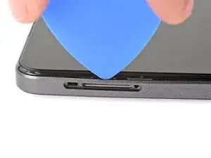
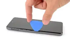
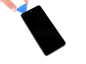
    • Insert the tip of an opening pick between the back cover and frame, at the SIM card tray cutout.

    Insert the pick between the glass screen and the side of the phone.

    James Huggett -

  4. nRAAoHrroh5koiF1
    nRAAoHrroh5koiF1
    xxLtuYjxIwIpuDqR
    gLRwvVvXUBnTYoll
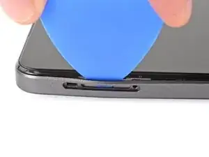
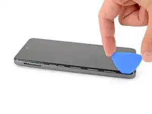
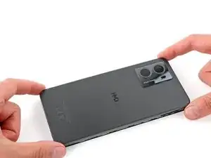
    • Position the opening pick straight down and slide it along the left edge to begin unclipping the back cover.

  5. CWFAAu5sb2OWIQ6N
    CWFAAu5sb2OWIQ6N
    MTiEIhZeqRENG3pB
    bsQYximLKu5HIuDJ
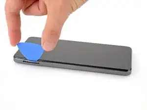
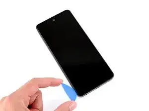
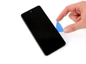
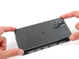
    • Continue sliding the pick around the perimeter of your phone until the back cover is fully unclipped.

    • The corners can be tricky to unclip and may take some force. If you're having trouble, try prying up with the pick.

    • Don't try to fully remove the cover yet, as a delicate cable still connects it to your phone.

  6. wdKfeBbKTeGQhTwx
    wdKfeBbKTeGQhTwx
    GGrANY1YqmMcSDnr
    Ldk3QiSaHAdqPAkT
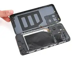
    • Carefully flip your phone over so the back cover is facing up.

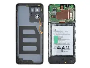
    • Lift the back cover off the frame and flip it over the left edge of your phone, laying the cover flat on your work surface.

    • Be very careful not to strain the back cover's delicate cable.

    • During reassembly, place the back cover onto the frame and firmly squeeze around the perimeter to reengage all the clips.

  7. OQklXUC4SLaJTZwB
    OQklXUC4SLaJTZwB
    nWHilWycIshpVfFs
    • Be very careful not to puncture the battery with your screwdriver.

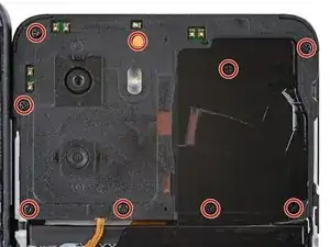
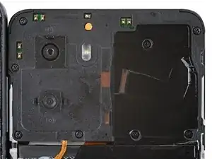
    • Use a Phillips screwdriver to remove the nine 3.6 mm‑long screws securing the motherboard cover.

    • The screw near the center of the top edge is covered by a sticker. Pierce through it with your screwdriver, or use tweezers to remove it.

  8. EfePFqdDo5UACwVR
    EfePFqdDo5UACwVR
    uulNPmeyhAAVPmkS
    KWIY4ByIZtUhPCMj
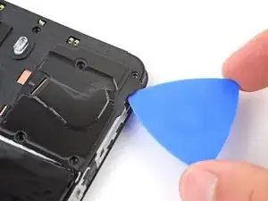
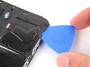
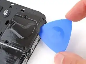
    • Insert an opening pick between the right edge of the motherboard cover and frame.

    • Twist the pick to fully unclip the cover.

  9. wwqvqPcYK3AJCfUs
    wwqvqPcYK3AJCfUs
    XSijYtLIP2gEWP2o
    • Remove the motherboard shield and its connected graphite sheet.

    • During reassembly, set the motherboard shield into place and press down firmly around the perimeter to reengage the clips.

  10. klMGnvivn2xa4txI
    klMGnvivn2xa4txI
    iRVAsmiqDH2DZcHU
    • Use the flat end of a spudger to pry up and disconnect the battery press connector from the bottom edge of the motherboard.

    • To reconnect these type of connectors, align the connector over its socket and press down with your fingertip—first at one side, then the other—until it clicks into place. Don't try to force the connector into place, or you may permanently damage it.

  11. wSRhFJpItNtO3R4x
    wSRhFJpItNtO3R4x
    6AckuLlJ6jQQLl3X
    • Use the flat end of a spudger to pry up and disconnect the back cover press connector from the bottom edge of the motherboard.

  12. 2douZZTJGn4SxPYW
    • Remove the back cover.

  13. fvsN6IrCaHSQ4IgJ
    fvsN6IrCaHSQ4IgJ
    fORUTfHwj6BmHXfB
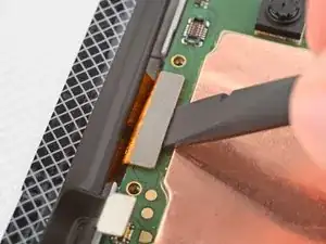
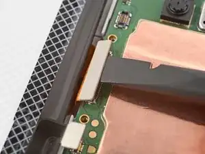
    • Use the flat end of a spudger to pry up and disconnect the display cable press connector, next to the battery cable.

  14. qsiok6SQeYQIoAVv
    qsiok6SQeYQIoAVv
    Cw1HDByfhXT2LwVQ
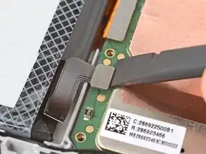
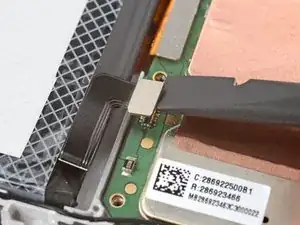
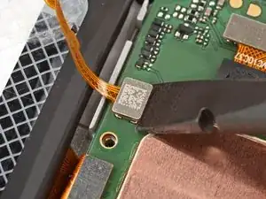
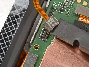
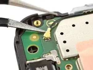
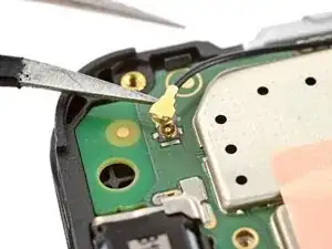
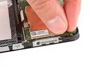
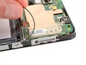
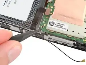
    • Slide one arm of a pair of tweezers under the metal neck of the black antenna cable's connector head, near the top right corner of the motherboard.

    • Lift straight up to disconnect the cable.

    • To reconnect the cable, hold the metal head over its socket and press down with the flat end of a spudger—it should snap into place. If it's not connecting, reposition the metal head and try again.

  15. gPMlgDcWXTQLUaqt
    gPMlgDcWXTQLUaqt
    gd4Cm2JIKHksnNKw
    • Gently pull the antenna cable out of its two clips on the right edge of the motherboard.

  16. CLQNYCDBuwBA33HS
    CLQNYCDBuwBA33HS
    lPx5OT5M26mOOhY4
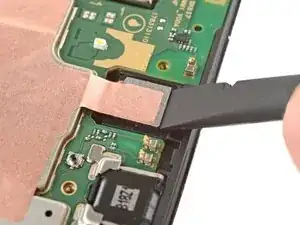
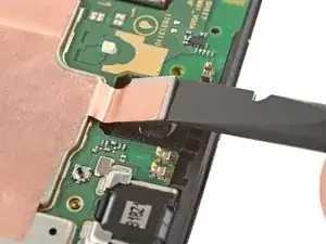
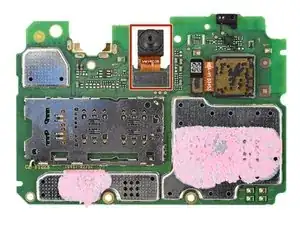
    • Insert the flat end of a spudger under the top edge of the front camera and gently lift it out of its recess.

    • Don't try to remove the camera, as it's connected to the bottom of the motherboard.

    • During reassembly, push down on the front camera until it's snug in its recess.

  17. LokAyb21sWaNpxFA
    LokAyb21sWaNpxFA
    q3Hgfm4Vxrk4bNOI
    kDlNFWA2C2uLPd6W
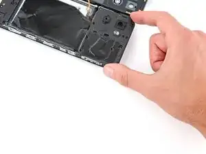
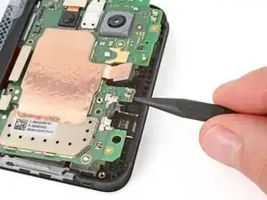
    • Use the point of a spudger to pry up the bottom right corner of the motherboard until it unclips.

    • If the board still feels stuck in place, use the spudger to pry up the top edge.

  18. qJFgM1AHD2ulP3u1
    qJFgM1AHD2ulP3u1
    nwUT1UrQ3PgkUxP6
    MrQY4DFMbC1BFSZR
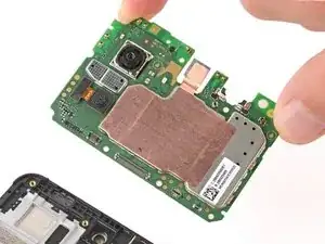
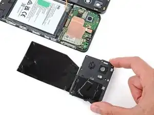
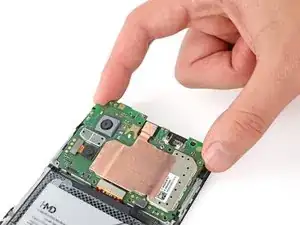
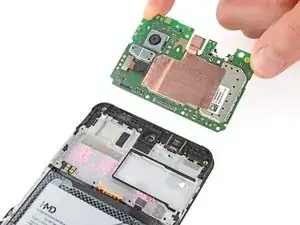
    • Lift and remove the motherboard.

    • The front camera may have disconnected from the bottom of the board during removal. If it did, reconnect its press connector.

    • During reassembly:

    • Make sure the two press connectors on the bottom edge and the antenna cable on the right edge are out of the way so they don't get trapped underneath the board.

    • Lower the board into its recess and press down on the edges to clip it into place.

  19. atyNnOmsOSCSEuve
    atyNnOmsOSCSEuve
    vt6qFwKvZurGWeDK
    VQbRZE5nFi6YnCRM
    • During reassembly:

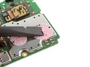
    • Use the flat end of a spudger to scrape off any large chunks of thermal paste from the bottom of the motherboard.

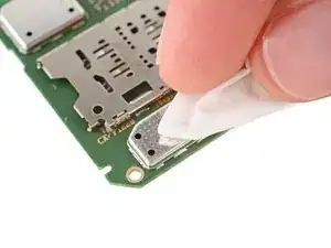
    • Use a pipette or syringe to apply a drop of isopropyl alcohol (>90%) to the thermal paste residue.

    • Wipe away all the residue with a coffee filter or lint-free cloth. Wait one minute to allow the alcohol to completely dry.

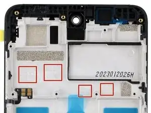
    • Apply a small bead of thermal paste to each of the four plus (+) signs that are lightly engraved in the frame.

  20. ptwA2QrNxagbI1NF
    ptwA2QrNxagbI1NF
    PHMBcJPJLBjEwTMn
    A5GXL2CDdTUBDEkw
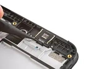
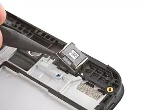
    • Use a spudger to pry up the earpiece speaker from the bottom edge of your phone.
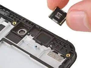
    • Remove the speaker.

    • During reassembly:

    • Remove the plastic liner from the earpiece speaker adhesive on the screen and frame assembly.

    • Push the speaker into place so the raised ends of its metal contact arms are on the bottom edge.

  21. qJ5SXI1MOLUZIEfD
    qJ5SXI1MOLUZIEfD
    uiXik1eegEhDGmPj
    STQjyZmLpsZyYXVp
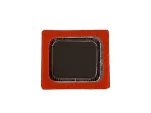
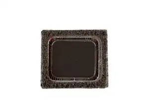
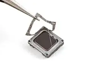
    • Use tweezers to carefully remove the layer of foam adhesive from the perimeter of the earpiece speaker's underside.

    • Discard the adhesive—it can't be reused.

    Use the spudger to scrape off the adhesive if the foam falls apart.

    James Huggett -

Conclusion

To reassemble your device, follow these instructions in reverse order.

Spencer Day

Member since: 14/09/22

88286 Reputation

0 comments