Introduction

  1. gYVGSr1JN3HUKukN
    gYVGSr1JN3HUKukN
    VVvPfXaYHDNZcH2R
    5LCGjOfTCViEI4Ih
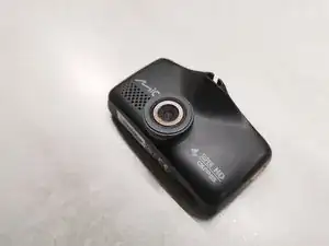
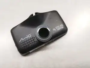
    • We will disassemble Mio MiVue 698 (Dual) car camera in this guide.

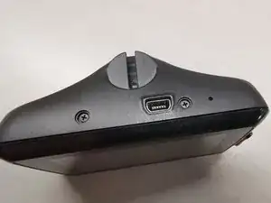
    • On the top of the unit, under the two caps, there are two Philips screws. Remove those caps and use Philips 0 screwdriver.

  2. oFBRVFCKxC4oUutM
    oFBRVFCKxC4oUutM
    LtSA4UGbDDxQGxNi
    YEGEqLcDudSaXCgu
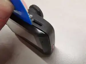
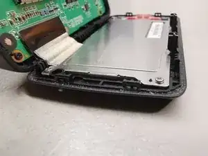
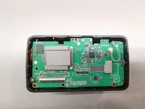
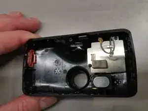
    • Now use a prying tool and gently pry all four sides of the display assembly.

    • Be careful not to damage the wire strip on the bottom.

  3. tPMssketKSO63RpA
    tPMssketKSO63RpA
    PkNlC3qX2sZTXRye
    vwOYNdKSCYsy5YRk
    • Remove black adhesive tape from the contacts.

    • Use a plastic tweezers to gently unlock wire strip from the contacts. You will end up with a disconnected display assembly.

  4. bfmkMkVGKr4P4sVi
    bfmkMkVGKr4P4sVi
    lsQUAIJbHCc5BCVA
    FG6uBFQQ1fo3fHP1
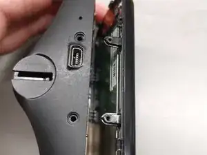
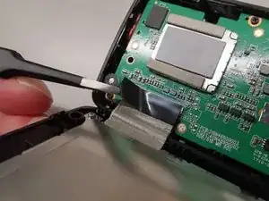
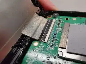
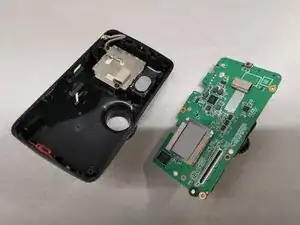
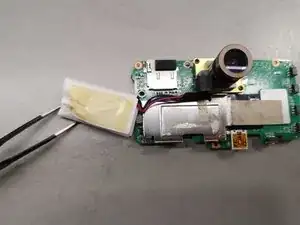
    • Disconnect the grey wire, which leads to GPS module.

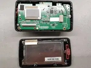
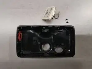
    • Remove three screws that hold the PCB.

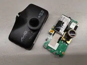
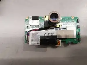
    • Remove the microSD card from the unit. Now you have to use a finger to carefully push against the lens from the front of the car camera, so the board will pop out.

    J'ai effectivement poussé avec un doigt sur l'objectif, mais j'ai aussi soulevé délicatement le plastique noir au niveau de la prise pour dégager le circuit complet.

    Vincent Lafontaine -

  5. CpRGaZ5yXtXUbgFM
    CpRGaZ5yXtXUbgFM
    Y2MjRLkGTViIKvVt
    • The battery is attached to the board with a small piece of tape.

    La prise de la batterie se trouve en-dessous de la plaque métallique sur laquelle elle est collée, il faut donc défaire les 2 vis. Au niveau de l'objectif, il y a un mousse à retirer, il colle légèrement et un tape, je l'ai décollé avec délicatesse au niveau de l'objectif. J'ai retiré la fiche de l'ancienne batterie en tirant légèrement sur le câble, et j'ai remis la nouvelle avec la pince. Après, j'ai remis le tape, le mousse et resserrer les 2 vis. J'a pris un peu de tape recto-verso pour coller la nouvelle batterie (l'ancienne était fort gonflée donc prudence en la retirant)

    Vincent Lafontaine -

  6. jFF2rnvXfinVEE5Y
    jFF2rnvXfinVEE5Y
    oO1kCRPusmN2SfpZ
    SFPTGtelG5CAEgsN
    • Remove two screws so you can remove the GPS module.

    J'ai remarqué que le boîtier s'écarte seul après avoir resserré les vis. Il faudrait peut-être mettre un léger joint sur le bord du boîtier, une sorte de colle comme on met sur les gsm mais pas trop forte. A voir.

    Le modèle réparé est la Mio 618, mais on dirait la jumelle de celle présentée. Donc même process

    Vincent Lafontaine -

Conclusion

To reassemble your device, follow these instructions in reverse order.

Peter

Member since: 23/01/22

163 Reputation

0 comments