Introduction

This guide will go over how to replace the power button, volume button, and left speaker unit on the Microsoft Surface Pro 5. The iOpener is used in this guide, but a hair dryer or heat gun could also be used. See instructions for the iOpener here.

  1. XIMh4MSksh44pNNd
    XIMh4MSksh44pNNd
    BUbRDHFYJ1XrOduS
    IGYPYU2BFYtiSqNb
    • Use a spudger to flip up the small locking flaps on the display cable ZIF connectors.

  2. j3K3PC2SWtrTCNwj
    j3K3PC2SWtrTCNwj
    iXRYKp6GmIcJHUip
    ZSKcipFPNmRUwXYU
    • Use tweezers to slide the display cables straight out of their sockets on the display board.

  3. NjWQGwgP12wvrc2x
    NjWQGwgP12wvrc2x
    BImRFqCTYboM2XSF
    PfDgyOLhXJNMXUsQ
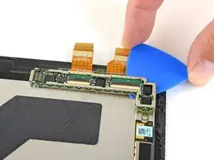
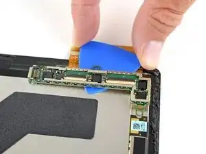
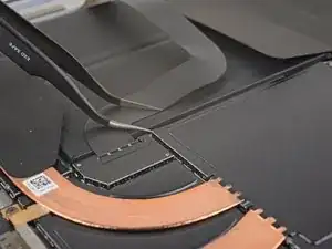
    • Slide an opening pick under the display board to separate the adhesive holding it onto the back of the screen.

  4. 1TMAZDapoXaJrogH
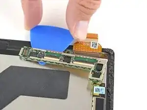
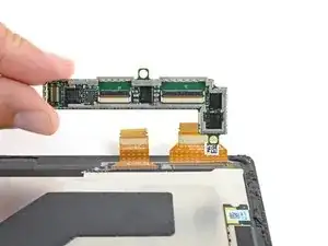
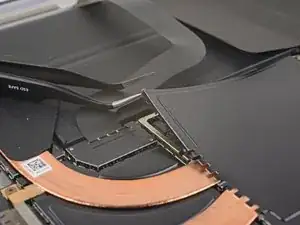
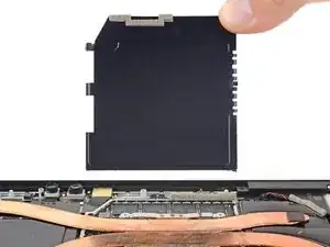
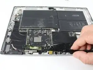
    • Remove the display board.

    • During reassembly, use a strong double-sided tape or a precut adhesive card to secure the display board. Clean off the old adhesive before applying new adhesive.

    • To ensure correct positioning, plug in both display connectors before adhering the board to the display.

  5. vyMI12oyMZcICDRS
    • Only the screen remains.

    Note, on the flex connectors of the new screen are blue strips of protective plastic covering factory applied conductive adhesive. These must be removed and the adhesive must bond to the display board in order for the touch screen digitizer to function reliably.

    Bill Mills -

  6. ZS3ZWfiENUv3SUSh
    ZS3ZWfiENUv3SUSh
    XAYHV1mQxRaXmO1f
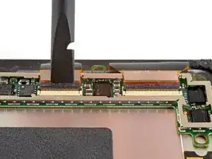
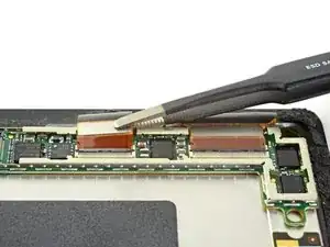
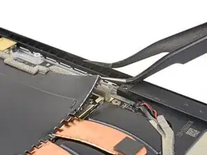
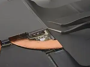
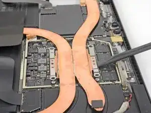
    • Insert one point of a pair of pointed tweezers into a gap in the corner of the EMI shield covering the heat sink.

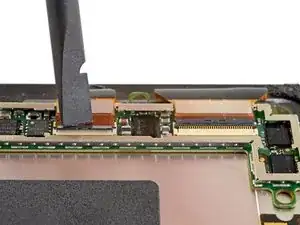
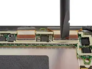
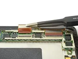
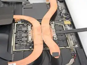
    • Use the tweezers to pry the EMI shield away from the motherboard as much as you can without bending it. Do not remove it yet.

    • Try not to deform the shield too much—you will need to reinstall it during reassembly.

    • Take care not to puncture the battery with the tweezers while working on this shield.

    Black spudger worked best to get the emu shields out without damaging them.

    Randall Takahashi -

  7. haKGWfQvAjOqcmop
    haKGWfQvAjOqcmop
    BAvJFLQ6cJTZ5kgg
    QtmksxCdQw2RVVAJ
    • Repeat the last step for each corner of the EMI shield covering the heat sink.

  8. HMKTfZaB1RPfuM3D
    • Remove the heat sink shield.

  9. grkamS26BKkLRpnf
    grkamS26BKkLRpnf
    NdknSlp6ynwrQPlH
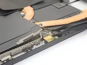
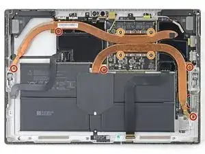
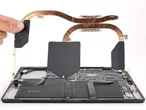
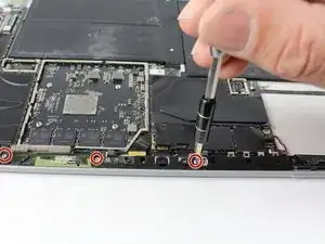
    • Remove the ten Torx screws securing the heat sink:

    • Five 2.6 mm-long T3 screws

    • Four 3.3 mm-long T5 screws
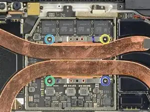
    • During reassembly, tighten the heat sink screws in the following criss-cross pattern, one turn at a time, until they're tight:

    • Screw 1

    • Screw 2

    • Screw 3

    • Screw 4

    Just like to add, on my i7, there is a fan in the top left corner and the heat sink is glued to the cover. The cover must be removed using a ph0 x 3 and one T3 (I think that is the sizes)

    Richard Wellesley -

    As the other person commented, mine also had a fan connected to the heatsink. This is present in the version with an Intel Core i7-7660U. It requires removing a T3 and T5 screw and the fan connector. Below is a link to an image showing this step.

    Surface Pro 5 with fan

    Brian T -

    While I do not have the fan present in my i5 version, the copper heat pipe does extend further down on the far left side (as oriented in the picture). There is an additional T3 screw on this arm as well as a small dab of adhesive on the very end.

    Emma Strainis -

    My i5 surface pro 5 has 6 of the T3 screws as the heat sink extends slightly further down.

    Joshua Dunsire -

  10. FtjL3iHlpcxfUYba
    FtjL3iHlpcxfUYba
    QLsZc6TXW6VPRbMJ
    lPyXn1ZrMJXnGQej
  11. M1Y4EKDKOwXsUdJq
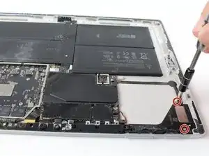
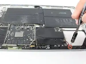
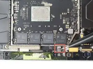
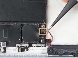
    • Remove the Torx T5 x 6mm screw connecting the black tie bar to the power button/volume control/speaker assembly.

  12. TGPFRVHSTCZrDLcw
    • Remove the remaining three Torx T5 x 4.5mm screws holding down the camera tie bar.

  13. qXfPHjwPdC1PQoFM
    • Disconnect the small ribbon cable connecting the camera tie bar to the motherboard by pulling up with tweezers.

  14. o5LxZnWDAjkLijux
    • Lift the camera tie bar off of the device.

  15. bl1gV1XyMKSLO5Op
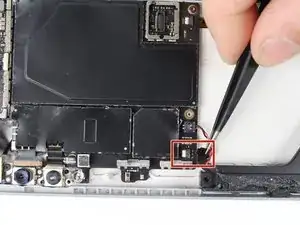
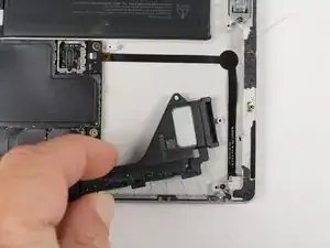
    • Use a Torx T5 to remove the two 4.5mm silver screws on the power button/volume control/speaker assembly.

  16. tPWqhXLQLrpJ4qUo
    tPWqhXLQLrpJ4qUo
    GcffYufCjAGAkYUC
    • Disconnect the small ribbon attaching the assembly to the motherboard by lifting up with tweezers.

    • Disconnect the black and red cable connector by lifting up with tweezers.

  17. yk1eA6QL2iQwPflN
    • Pull the assembly to the left with hands and lift up to remove.

Conclusion

To reassemble your device, follow these instructions in reverse order.

Kaden Foster

Member since: 02/10/17

885 Reputation

One comment

Hi,

Where can I purchase the power button assembly in the UK?

junaidpatel -