Introduction
The camera tie bar mounts the front and rear cameras as well as providing additional mounting support for the right and left speakers. It also connects to the motherboard via a small ribbon cable.
-
-
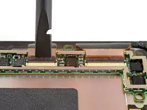
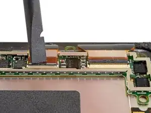
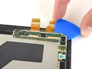
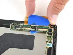
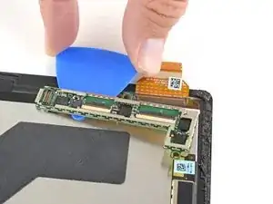
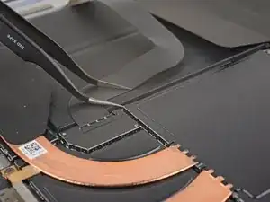
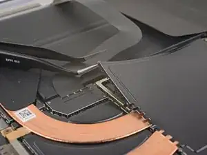
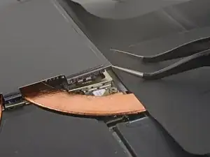
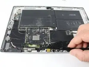
Slide an opening pick under the display board to separate the adhesive holding it onto the back of the screen.
-
-
-
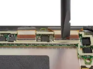
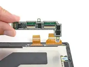
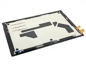
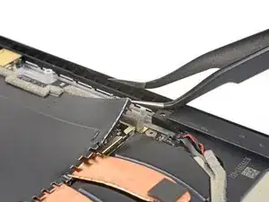
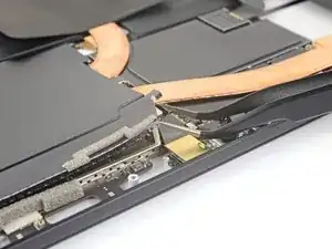
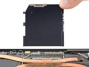
Remove the display board.
-
To ensure correct positioning, plug in both display connectors before adhering the board to the display.
-
-
-
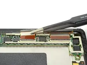
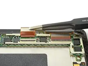
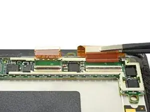
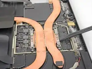
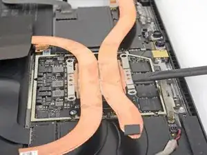
Insert one point of a pair of pointed tweezers into a gap in the corner of the EMI shield covering the heat sink.
-
Use the tweezers to pry the EMI shield away from the motherboard as much as you can without bending it. Do not remove it yet.
-
-
-
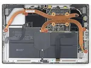
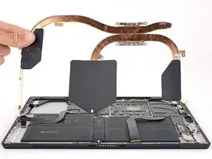
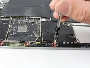
Remove the ten Torx screws securing the heat sink:
-
Five 2.6 mm-long T3 screws
-
Four 3.3 mm-long T5 screws
-
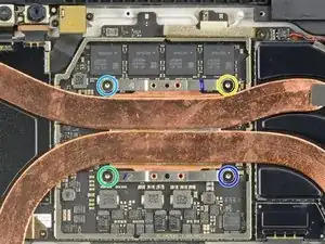
Screw 1
-
Screw 2
-
Screw 3
-
Screw 4
-
-
-
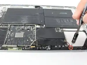
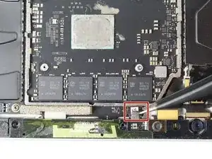
Remove the Torx T5 x 6mm screw connecting the black tie bar to the power button/volume control/speaker assembly.
-
To reassemble your device, follow these instructions in reverse order.
2 comments
Do you really need to remove the heat sink shield and the heat sink to disconnect the tie bar small ribbon cable ?
round rubber?
MANUEL -