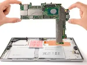
Introduction
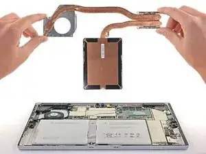
Follow this guide to replace the motherboard on a Microsoft Surface Pro 4.
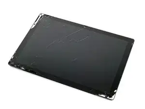
There is a significant chance that you may break the unreinforced and fragile display panel during this procedure. Be sure to apply adequate heat and be extremely careful while slicing through the adhesive. Wear safety glasses in case the glass shatters.
Applying new thermal paste during reassembly may improve the performance of your Surface. If you wish to do that, make sure you have new thermal paste and either high-concentration isopropyl alcohol or a specialized thermal paste cleaner.
-
-
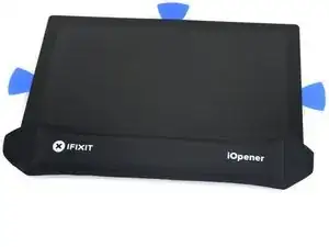
If your screen glass is cracked, keep further breakage contained and prevent bodily harm during your repair by taping the glass.
-
Lay overlapping strips of clear packing tape over the Surface’s screen until the whole face is covered.
-
Do your best to follow the rest of the guide as described. However, once the glass is broken, it will likely continue to crack as you work, and you may need to use a metal prying tool to scoop the glass out.
-
-
-
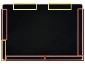
Take note of the screen adhesive layout before continuing:
-
These areas only contain adhesive and are safe to cut.
-
The display board and flex cables sit here close to the edge. Cut carefully and don't insert the pick more than 1/8 inch (3 mm).
-
Fragile antenna cables lie under this part of the screen. Carefully follow the procedure in step 13 to avoid damaging them. The adhesive is also the thickest here.
-
-
-
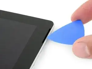
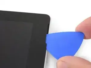
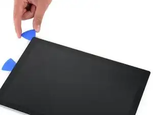
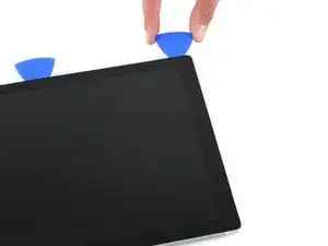
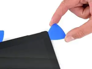
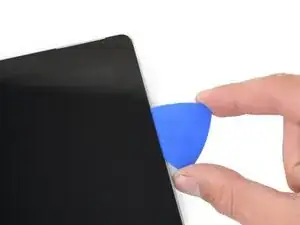
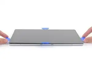
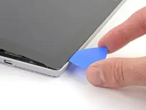
Insert an opening pick into the top-right speaker cutout on the screen and slide the pick between the glass and speaker grille.
-
-
-
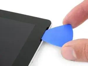
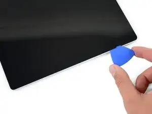
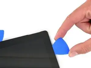
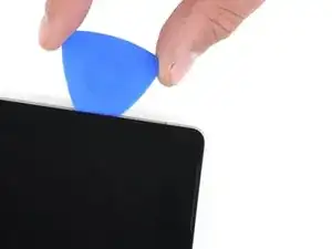
Rotate the pick toward the bottom of the Surface to slide it underneath the lower edge of the speaker cutout.
-
-
-
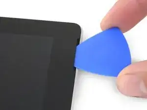
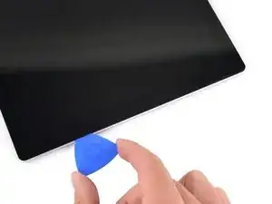
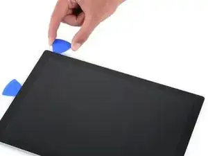
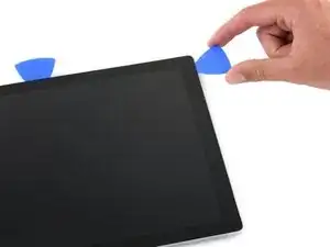
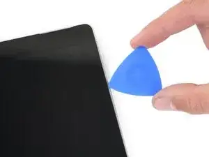
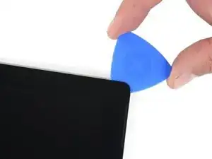
Slide the pick down the right edge of the Surface to slice through the adhesive under the screen.
-
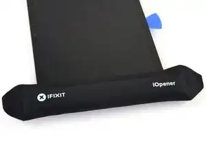
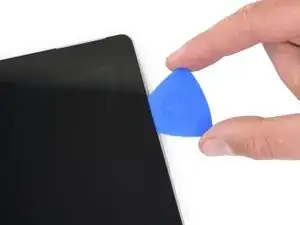
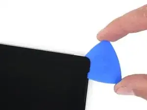
Leave this opening pick in the right edge to prevent the adhesive from resealing.
-
-
-
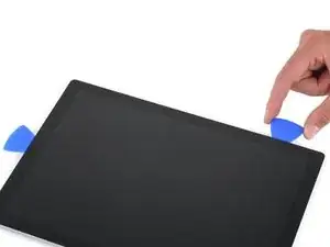
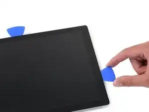
Insert a new opening pick into the bottom-right corner and slide it around the corner toward the bottom edge.
-
Slide the pick along the bottom edge of the Surface to cut through the screen adhesive.
-
Leave this pick in the bottom edge to prevent the adhesive from resealing.
-
-
-
Insert a new opening pick into the bottom left corner and slide it around the corner toward the left edge.
-
Slide the pick along the left edge of the Surface to cut through the screen adhesive.
-
Leave this pick in the left edge to prevent the adhesive from resealing.
-
-
-
Round the left corner with the opening pick and slide it along the top edge of the Surface. Stop when the pick is 2.75 inches (70 mm) away from the left edge.
-
-
-
Insert the point of a pick under the screen where you just stopped cutting. Don't insert the pick deeper than the edge of the bezel.
-
Carefully roll the pick to the right, pressing the long edge of the pick into the screen adhesive underneath the bezel, cutting the adhesive as you go. Don't slide the pick along the edge of the Surface.
-
Repeat this motion of inserting the point of the pick where you just cut, and rolling to the right all along the top edge of the Surface, until the pick is 2.5 inches (64 mm) from the right edge of the Surface.
-
-
-
Once you cut the adhesive over the antennas (8.5 inches, or 22 cm, from the left edge), slide the pick the rest of the way along the top edge of the surface and round the top right corner to slice through any remaining adhesive.
-
-
-
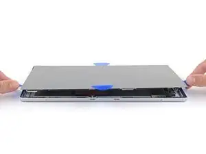
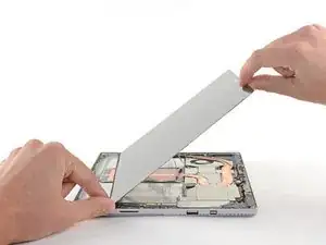
Very slowly lift the screen assembly away from the Surface case. If you encounter any resistance, stop and check that all the adhesive is separated.
-
Use an opening pick to cut through any remaining adhesive.
-
-
-
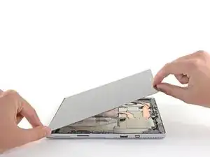
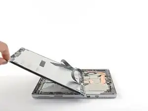
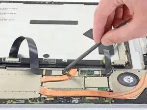
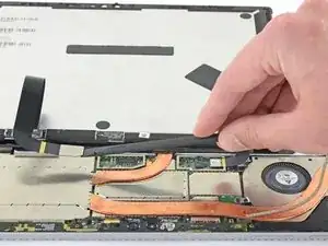
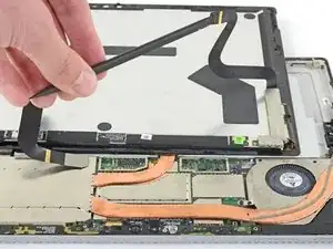
Lift the top of the screen assembly away from the case while sliding the bottom of the screen closer to the motherboard display connectors.
-
Gently lay the screen down on the case with the connectors facing up. Take care to avoid creasing the display cables.
-
-
-
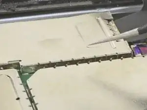
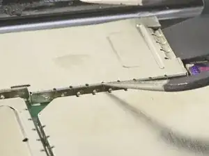
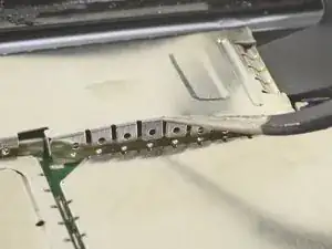
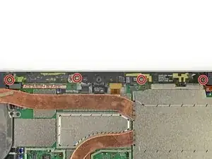
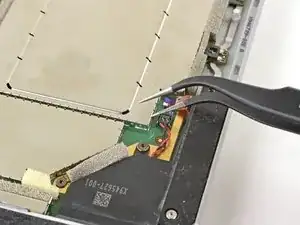
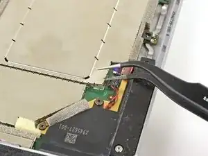
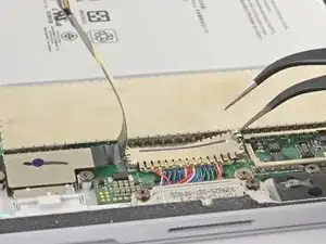
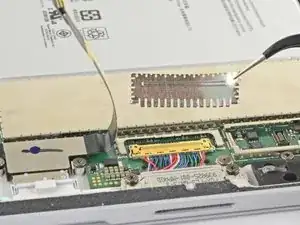
Use one tip of a pair of angled tweezers to pry up the EMI shield from the gaps between the "teeth."
-
Repeat this procedure at different points around the perimeter of the shield until it is free.
-
-
-
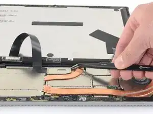
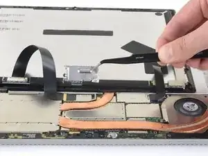
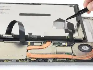
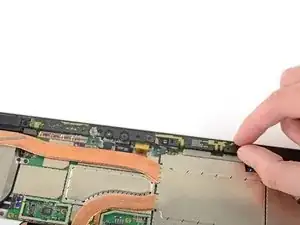
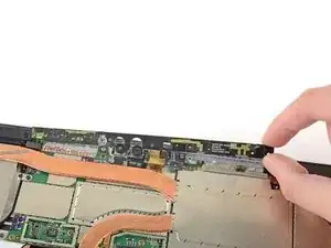
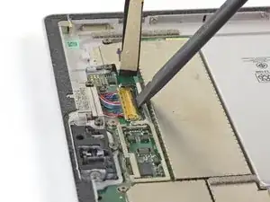
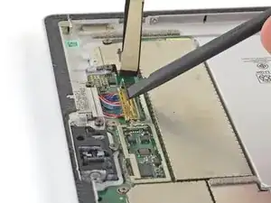
Pry up with the flat end of a spudger to disconnect each display cable from the motherboard.
-
-
-
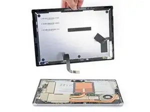
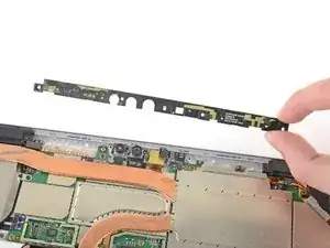
Remove the screen from the Surface.
-
During reassembly, pause here and follow this guide to replace the screen adhesive.
-
-
-
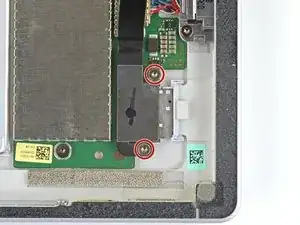
Use a T5 Torx screwdriver to remove the four 4.5 mm screws securing the antenna support bracket.
-
-
-
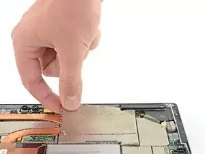
Insert one point of a pair of pointed tweezers into a gap in the corner of the EMI shield covering the heat sink.
-
Use the tweezers to pry the EMI shield away from the motherboard as much as you can without bending it. Do not remove it yet.
-
-
-
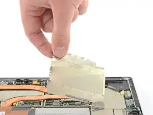
Repeat the last step at various locations around the perimeter of the EMI shield covering the heat sink.
-
Remove the CPU shield.
-
-
-
Use a T3 Torx screwdriver to remove two screws from the heat sink:
-
One 2.4 mm screw along the top of the rectangular plate covering the battery.
-
One 2.2 mm screw along the bottom of the rectangular plate covering the battery
-
-
-
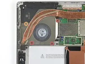
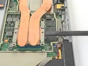
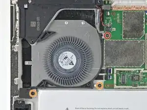
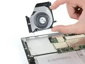
Use a Phillips screwdriver to remove three 2.4 mm screws securing the fan.
-
Use a T5 Torx screwdriver to remove the final 4.4 mm screw securing in the fan cover.
-
-
-
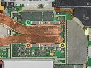
Use a T5 Torx screwdriver to remove the heat sink screws surrounding the CPU in the following pattern, one turn at a time, until they're free.
-
Screw 1
-
Screw 2
-
Screw 3
-
Screw 4
-
-
-
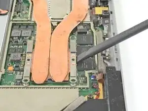
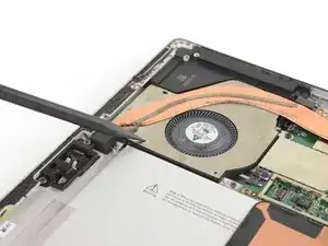
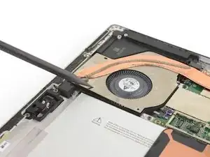
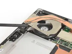
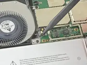
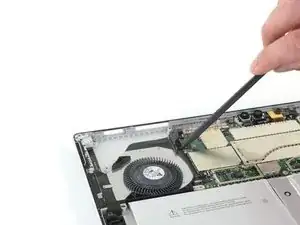
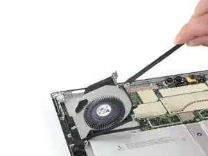
Insert the pointed end of a spudger into a screw hole in the fan shield and lift up to separate it from the fan.
-
-
-
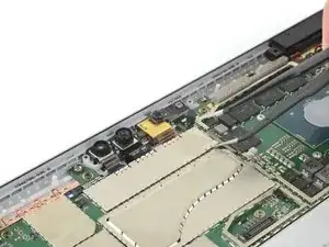
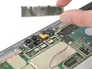
Insert one point of a pair of pointed tweezers into a gap in the corner of the EMI shield covering the camera connectors.
-
Use the tweezers to pry the EMI shield away from the motherboard as much as you can without bending it.
-
Remove the EMI shield.
-
-
-
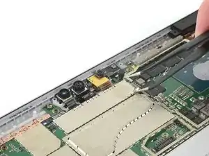
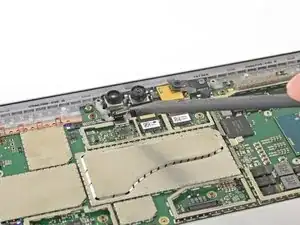
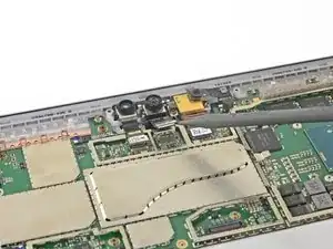
Pry up with the pointed end of your spudger to disconnect all three camera cables from the motherboard.
-
-
-
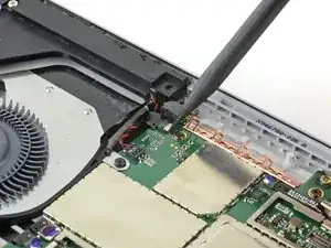
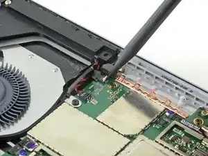
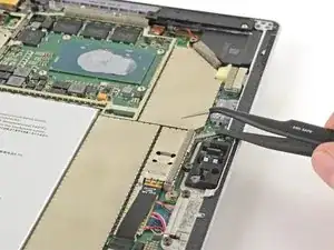
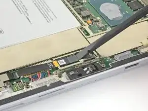
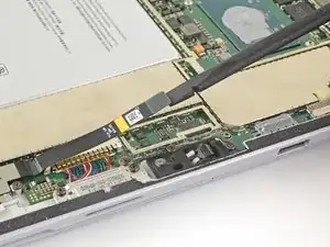
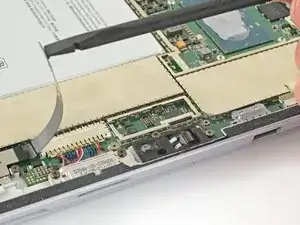
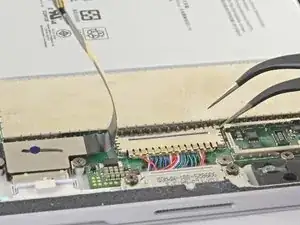
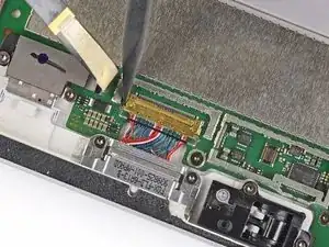
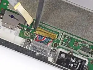
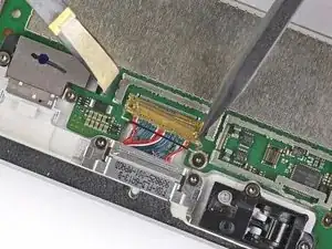
Use the pointed end of your spudger to unlock the ZIF connector securing the volume/power button cable.
-
Gently slide the volume/power button cable out of the ZIF connector.
-
-
-
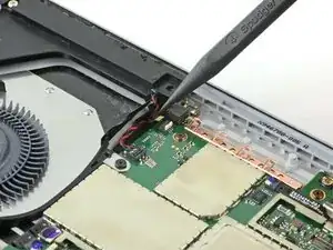
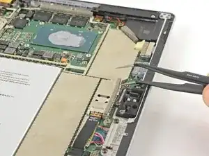
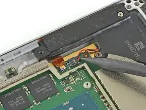
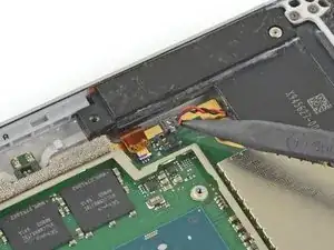
Slide the pointed end of a spudger between the speaker wires and the motherboard until it is resting against the speaker wire connector.
-
Carefully pry straight up on the speaker wire connector to disconnect it from the motherboard.
-
-
-
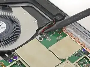
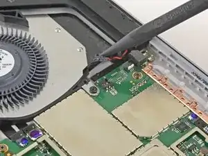
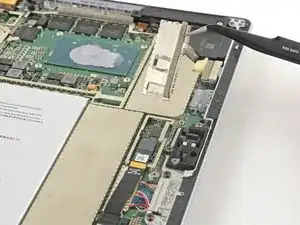
Use the pointed end of your spudger to gently slide the fan and headphone jack cables out of their ZIF connectors.
-
-
-
Use a T3 Torx screwdriver to remove the following screws from the fan:
-
One 2.5 mm screw with coarse threads
-
Two 2.4 mm screws
-
-
-
Use the flat end of your spudger to lift the microSD card reader's connector straight up out of its socket.
-
Lift the microSD card reader cable up and out of the way of the EMI shield covering the charging assembly.
-
-
-
Insert one point of a pair of tweezers into a gap in the edge of the EMI shield covering the charging assembly cable connector.
-
Use the tweezers to pry the EMI shield away from the motherboard as much as you can without bending it.
-
Remove the shield.
-
-
-
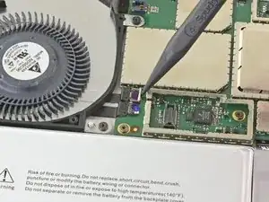
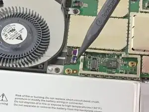
Use the flat end of a spudger to flip up the retaining lock securing the charging assembly cable connector.
-
-
-
Use the tip of a spudger to carefully push on each side of the connector.
-
Alternating from one side to the other, gently "walk" the connector out of its socket.
-
-
-
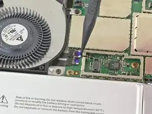
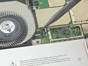
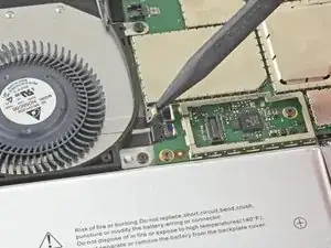
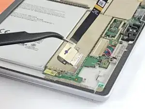
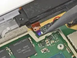
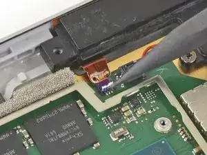
Use the pointed end of your spudger to unlock the ZIF connector between the processor and right speaker.
-
Disconnect the cable from the ZIF connector.
-
-
-
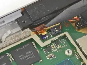
Slide the pointed end of a spudger between the right speaker wires and the motherboard until it is resting against the speaker wire connector.
-
Carefully pry straight up on the speaker wire connector to disconnect it from the motherboard.
-
-
-
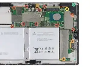
Use a T3 Torx screwdriver to remove the following screws from the fan and motherboard:
-
Ten 2.4 mm screws
-
Two 2.2 mm screws
-
Use a T5 Torx screwdriver to remove the two screws securing the right speaker:
-
One 4.2 mm screw
-
One 6.0 mm screw
-
-
-
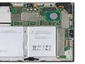
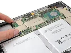
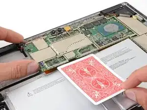
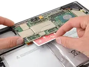
Slightly lift the left edge of the motherboard.
-
Insert a playing card or similar object between the battery connector and the motherboard.
-
-
-
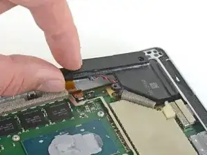
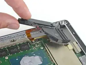
Grip the narrow section of the right speaker box and lift it up slightly.
-
Slide the right speaker back out of the chassis.
-
Remove the right speaker.
-
-
-
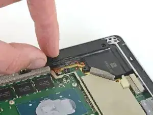
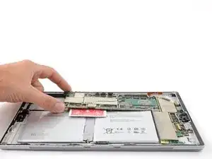
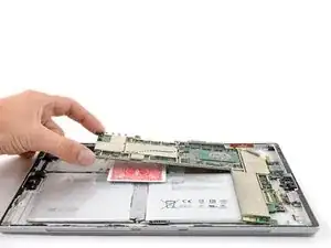
Remove the motherboard by first lifting the left side until it is at roughly a 30 degree angle.
-
Gently slide the I/O ports on the motherboard out from their openings and remove the motherboard.
-


To reassemble your device, follow the above steps in reverse order.
Take your e-waste to an R2 or e-Stewards certified recycler.
Repair didn’t go as planned? Try some basic troubleshooting, or ask our Answers community for help.

3 comments
Super Anleitung !
Tst -
awesome info; used it to strip four "broken" tablets and reassemble as three working tablets (Schottky diodes and bad batteries)
Un genio, paso por paso, muy didactico como pracico! Gracias por toda tu informacion me he dado cuenta que es un trabajo muy meticuloso y no es para andar a la apuradas! Realmente muchas gracias
If I have a screen protector on the screen should I remove it? Will it interfere with the heating process?
IronJoker -
I was wondering if I should put a screen protector on to help keep the screen from cracking???
Kevin -