Introduction

This guide will teach you how to safely remove the headphone jack from your Surface Pro 3. The guide starts by removing the screen and digitizer and then goes right into removing the headphone jack.

  1. IiLLy5RGqI2C21Fc
    IiLLy5RGqI2C21Fc
    JifXbRFswEYOyZhX
    • Before you begin, discharge the Surface Pro's battery below 25%. A charged lithium-ion battery can catch fire and/or explode if accidentally damaged during the repair.

    • The display is strongly glued to the frame of the device.

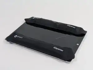
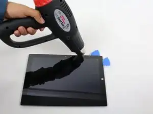
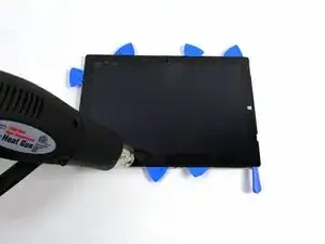
    • To remove the display, first soften the adhesive by applying heat. You can use a heat pad, heat gun, or iOpener. In a pinch, a hair dryer can also work.

    • Be careful when using a heat gun, as too much heat can permanently damage the display and/or battery.

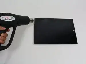
    • Steadily and evenly heat the perimeter of the display until it's too hot to touch, and try to maintain that temperature for several minutes.

    I just replaced both my screen and battery. It took four hours and a couple of wrong turns but I was successful learning what to do next time. However, I am not sure I would do it again.


    It takes more heat than one imagines - all most too much and made me queasy fearing I was going to damage something. I would say it actually too hot and likely to damage something so be careful and do not prolong the removal. To get started I used a glass top warming/buffet heating tray set to about 200 degrees.  I turned the surface pro glass side down before turning it one so it would heat gradually with the tray. I let it heat for 15 minutes. In end, I am not sure it helped or not by starting this way.  This was not an easy removal so I shudder to think how worse it would have been if this didn’t help. I used a variable heat gun for the remaining steps. My screen was broken so breaking it further while nerve racking was not going to be catastrophic.

    michael jones -

    I attempted battery replacement, but during disassembly, i damaged the display by inserting the picks to far, and separating the display circuitry from the glass.

    I used a Milwaukee precision hot tool model 1400, which has only a fixed heat setting, but it worked perfectly to soften the adhesive.

    (I was very careful to heat the entire glass panel by playing the heat gun over the entire surface so that it would expand uniformly.

    Robert Gerlach -

    I just broke mine during the heating process as well…. The glue at the corner was so strong that I cant even slip a blade into the edge… Then when keep applying heat using a hair dryer at low tempreture the glass expanded too much and broke……

    C Y Wong -

    If you have never done this repair, YOU WILL SHATTER THE SCREEN! I've repaired dozens of these over the last several years for my client's and I still shatter them. It's a 98% probability that you will break the glass; it's very thin and shatters easily. Be prepared.

    Gregg Stanley -

  2. tP1SBUeGkGMfOjX5
    tP1SBUeGkGMfOjX5
    Hbta2bLf13RFqrbk
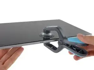
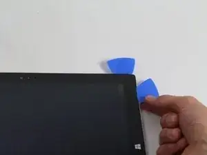
    • Use a suction cup or an iSclack to pull up on the glass and create a slight gap between the glass and the metal frame.

    • If your display is badly cracked, a suction cup may not adhere. It may help to first cover the display with a layer of packing tape. Alternatively, you can superglue your suction cup to the display.

    • Carefully insert an opening pick into the gap between the screen and the device to cut the adhesive.

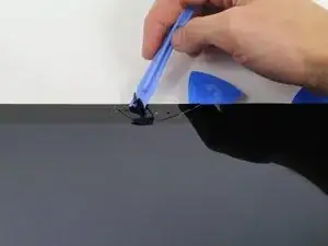
    • Slide the pick around the sides and bottom of the display to cut the adhesive. Apply more heat as needed.

    • Work carefully—the glass is thin and will crack easily if you try to force it.

    • The wi-fi antennas are glued under the screen border along the top edge (on either side of the camera), and can be damaged easily. Use extra care when separating the top edge, and apply more heat if necessary.

    Be very very careful!! Don’t cut yourself. Wear gloves.

    Vincent van Mens -

    Wear eye protection too!

    Zach -

  3. ITFJIC242QKNpVUA
    ITFJIC242QKNpVUA
    kOlisXUZbyYIkKPE
    hBFsBRIsH4VyHVeV
    • Continue to heat sections of the screen with the heat gun.

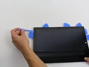
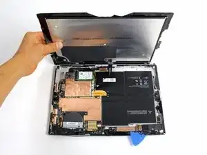
    • As you make your way around the screen with the heat gun, use the plastic opening tool and the opening picks to pry the screen loose.

    • The screen is extremely thin and very easy to break. Be careful working with broken glass.

    I used an inexpensive variable heat gun with a dial. It was perfect. My fixed temperature gun would have ruined it. There are two small vents on either side of the screen near the top. Start there and work down on each side. I didn’t have opening picks to keep the glass separated from the body. So, I used blank Cards Against Humanity I found lying around.

    I watched two popular videos. Neither helped and were no better than these instructions. In one video, the guy heats and smashes his way around the display with metal tool. Mistake! Don’t do this even if the screen is broken. This causes glass shards to go everywhere and will force you to replace the adhesive before installing a new screen. You can’t reuse adhesive if it is full of glass. Another video uses a heat gun one side at a time and simply sliding a pick along the edge working around the Surface. This didn’t work. The person had already removed the screen once before and started the second removal before the video.

    michael jones -

    CAUTION: if you insert the picks too far, you risk damaging the display (separating the glass from the display circuitry).

    The display circuitry is 14 mm from the side edges, 10 mm from the top edge, and 6 mm from the bottom edge.

    Robert Gerlach -

    thanks a lot for your comment

    philrillh -

  4. 2wnI62JYRjtwQyde
    2wnI62JYRjtwQyde
    XtSAtOnl55XIALpb
    • Lift the screen up carefully so that no wires are torn.

    This guide misses a CRUCIAL NOTE on this step.

    On this step, from Picture 1 to Picture 2 the device is rotated so the Windows logo on the glass is actually on the left hand side.

    You *must* rotate the device otherwise you will risk damaging the cables, as it folds open like a book.

    Len Demby, Jr. -

    Pain in the ass! One has to wonder why they couldn’t use magnetic connections instead of this goo, black thing that even to replace is so %#*@ annoying to say the least! After trying to remove a broken screen I didn’t even use the adhesive strips. I used the ones I had there and to be frank it’s better since:

    a) I couldn’t get the new screen properly aligned and to fit to perfection even though the touch works flawlessly (w/ some adhesive tape on the top to hide the gaps) and

    b) who knows? you may as well need to reopen it again. Hopefully not.Hopefully it will be easier. Hopefully never again!!!

    P.S.:

    Iraklis -

  5. JZKTg6AfXimEjrtV
    JZKTg6AfXimEjrtV
    ZnmLaLSWKZwXLQbk
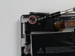
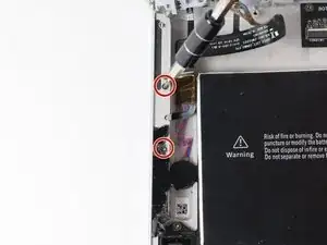
    • Remove the 3 mm T3 Torx screw securing the battery connector, and disconnect the battery connector.

    • Be careful not lose the small, rectangular bridge connector that lies underneath.

  6. iieXwVFQKStTJgx2
    iieXwVFQKStTJgx2
    FseWAjfVVlTtIElr
    EXtrTCBmBrFVHUF2
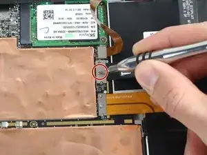
    • Remove the single 4 mm T3 Torx screw securing the display cable.

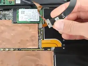
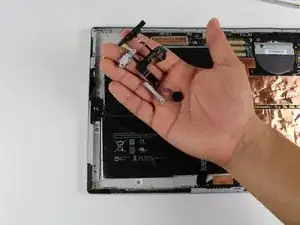
    • Lift the connector to disconnect the cable.

    • Be careful not lose the small, rectangular bridge connector that lies underneath.

    It's always best to disconnect the battery before disconnecting the display cable. Ensuring there is no power to the device will also ensure you don't damage the backlight components when disconnecting the display. You should also make sure to reattach the display cable before reattaching the battery cable when putting it back together.

    KCrepairguy -

    There is also a tiny little board between the ribbon cable and motherboard. Be sure not to lose it!!! If you do the part is 1631 LCD Contact Shield Plate.

    Joseph Neilson -

    You’ll notice a spring on the back of your old screen. The new screens don’t have that spring so it will need to be transferred over by the heat gun trick.

    Thierry Plouchart -

    The instructions do not mention the bridge connectors under the connectors - tiny little rectangle boards with gold connector dots. There is one under the battery connector and under the display connector. It is sandwiched in between the board and the connector. You may not even notice the bridge connectors. In fact the pictures here with the cable connectors off are showing the bridge connectors under the cable connectors still lying on the motherboard. Go ahead and remove the bridge connectors with tweezers. These connectors are just lying on the motherboard and WILL FALL OFF getting lost without noticing it. The cable connectors do not work without the bridge connectors installed. Good news is the connectors are keyed and fit only one way.

    BTW: Both screws on the battery and display connector were T3’s and the same size.

    michael jones -

    Hi!. What’s the name of the band connector and what’s the name of the connector in both sides?

    Nicolás Rearte -

  7. Z1WlbuZDAgkKVFiW
    Z1WlbuZDAgkKVFiW
    QNjSjbRDTeirpNKk
    YFw1T6xydkRpWpj4
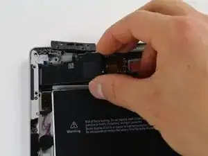
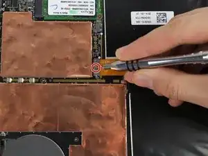
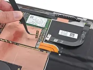
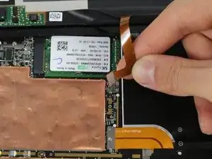
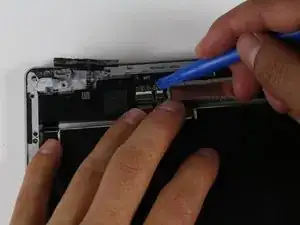
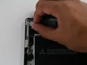
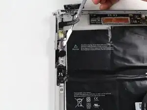
    • Grasp the orange cable connected to the silver connecter.

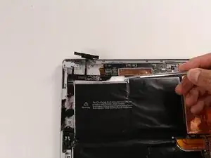
    • Carefully lift the orange cable up until the connecter pops off.

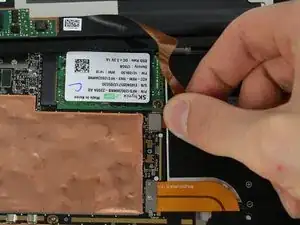
    • The screen will now be completely disconnected.

    • The replacement display may not include all the parts needed for installation. Save all the parts from the original display, and transfer them to the new display as needed.

  8. lZGJocBhXcxBRqFG
    lZGJocBhXcxBRqFG
    6BoVmVYcy551OE6l
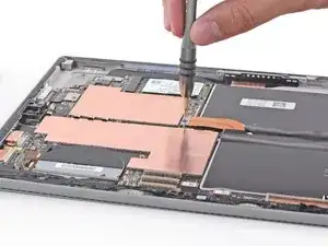
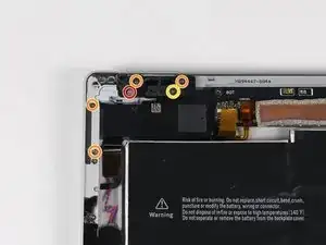
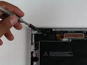
    • Remove the single 4 mm T5 Torx screw.

    • Remove the four 4 mm T3 Torx screws.

    • Remove the single 7 mm T3 Torx screw.

  9. bl4kD5JmslSSyX3h
    • Remove the nut with the 4mm nut driver.

  10. JpjKfSs1MZhIvkVQ
    JpjKfSs1MZhIvkVQ
    EOdLkJFPR1sfnjWp
    • Use the plastic opening tools to remove the black piece.

  11. G6YRPPfiqZPnHJQD
    • Carefully remove the gray headphone jack.

  12. 3GcjQRUE1VdXjHHj
    • Use the metal spudger to remove the black ribbon wire from the device.

  13. PHXPZeWiW4Py353X
    • Remove the two 4 mm T3 Torx screws.

  14. fsosxc6xo2ZUims1
    fsosxc6xo2ZUims1
    UVkHCWuhGSfAKwei
    • Finish removing the headphone jack using the metal spudger.

Conclusion

To reassemble your device, follow these instructions in reverse order.

Erik Snyder

Member since: 01/10/15

5366 Reputation

One comment

Very good instructions. But where is the difference between Headphone Jack Assembly with P/N

0801-35U00QS, 0801-35U01QS and 0801-2W900QS? On some of them is also X894488-001 printed in an extra row.

Daniel -