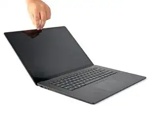
Introduction
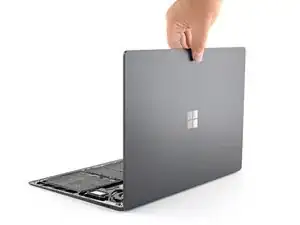
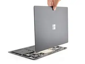
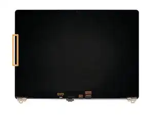
This guide demonstrates how to replace the LCD panel in your Microsoft Surface Laptop 3 (13.5").
Note: This guide demonstrates how to replace the LCD panel within the screen assembly. Make sure you have the panel by itself before following this guide. If you have the entire screen assembly (including the metal shell and screen hinges), follow this guide.
Remember to follow general electrostatic discharge (ESD) safety procedures while repairing your device.
Some photos in this guide are from a different model and may contain slight visual discrepancies, but they won't affect the guide procedure.
-
-
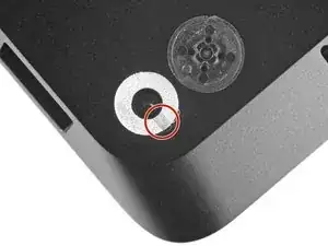
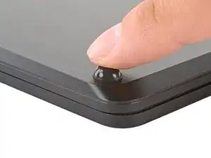
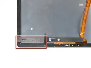
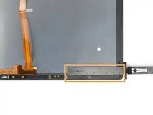
Each foot has a hidden indent that will simplify removal.
-
To make sure the spudger is in the indent, insert it at the nearest long edge, pushing parallel to the short edges of the laptop, as shown.
-
-
-
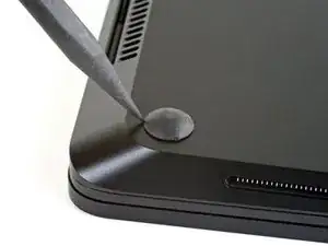
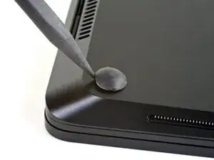
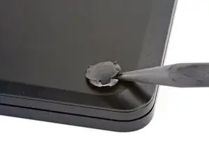
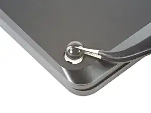
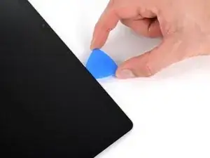
Insert the pointed end of a spudger underneath one of the two rear feet, at its rear edge.
-
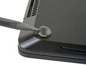
Push the spudger underneath the foot and pry up to release it.
-
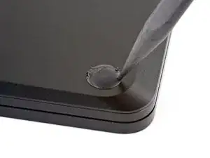
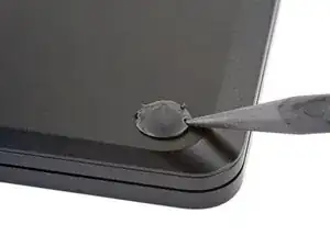
Repeat to remove the second rear foot.
-
-
-
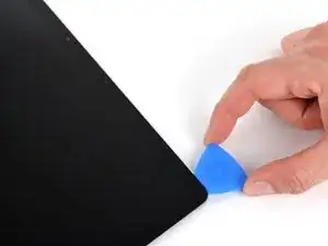
Insert the pointed end of a spudger underneath one of the two front feet, at its front edge.
-
Push the spudger underneath the foot and pry up to release it.
-
Repeat to remove the second front foot.
-
-
-
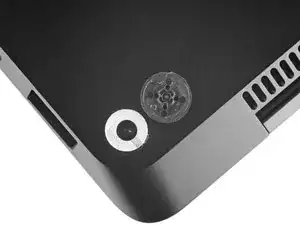
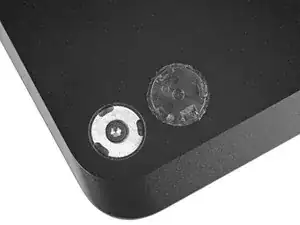
Note that the front and rear feet are different.
-
Note that the front feet are directional and only clip in one way.
-
-
-
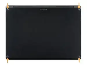
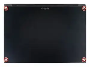
Use a T5 Torx driver to remove the four 3 mm screws in the foot cavities securing the upper case to the device.
-
-
-
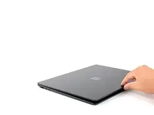
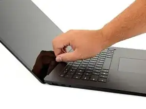
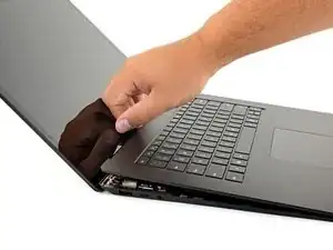
Grip the top edge of upper case above the keyboard and lift straight up to release it.
-
Lift the front edge of the upper case up and away from the laptop, taking care to not strain the keyboard and touchpad ribbon cable underneath.
-
-
-
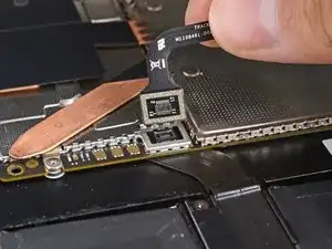
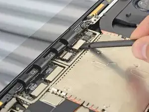
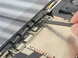
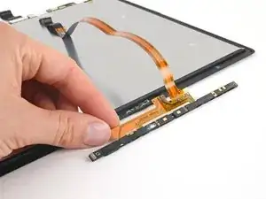
Insert the flat end of a spudger underneath one edge of the ribbon cable connector, and pry up to release it.
-
Remove the ribbon cable from the motherboard.
-
-
-
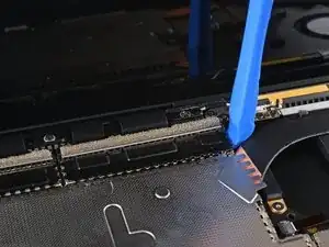
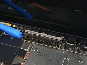
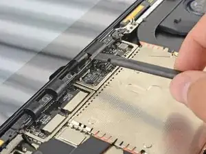
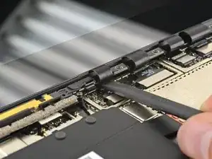
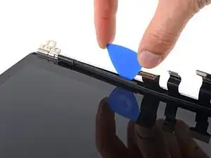
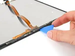
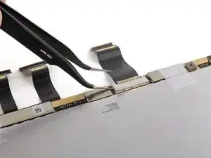
Use an opening tool to pry up the black shield covering the right bank of display connectors.
-
Repeat at different points around the shield until it becomes loose.
-
Remove the shield.
-
-
-
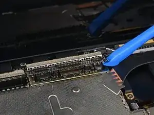
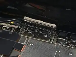
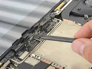
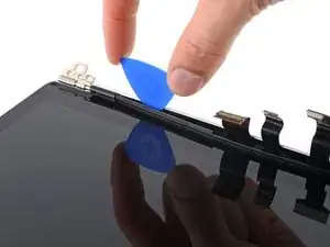
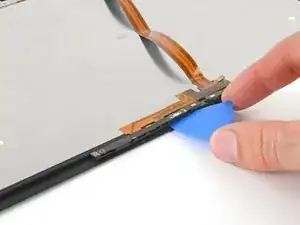
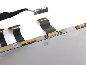
Repeat the previous step to remove the remaining shield from the left bank of display connectors.
-
-
-
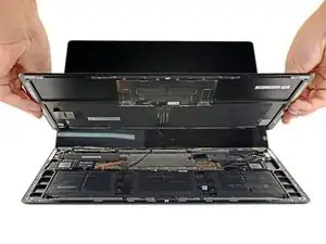
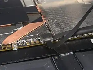
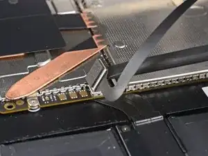
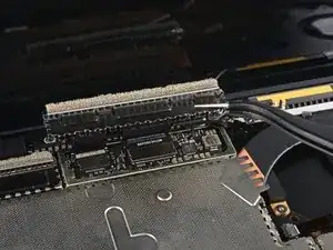
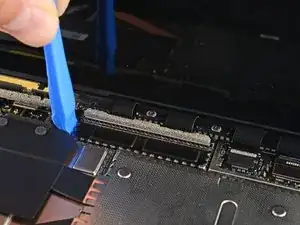
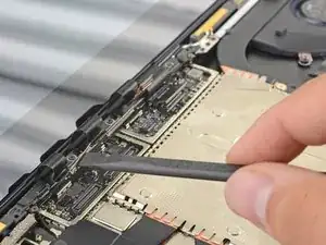
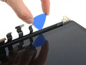
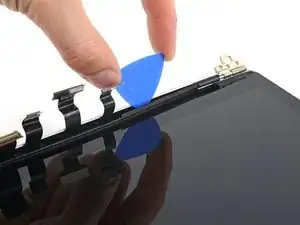
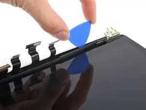
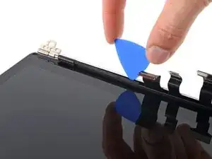
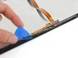
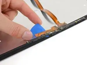
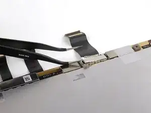
Use the flat end of a spudger to pry the first display cable up and out of its socket on the motherboard to disconnect it.
-
-
-
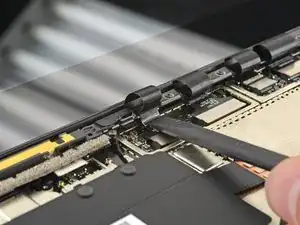
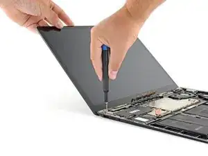
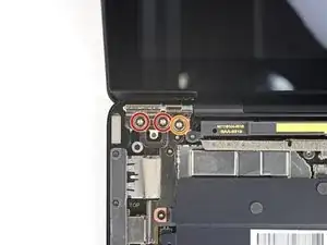
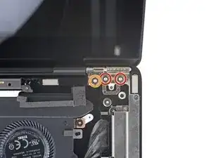
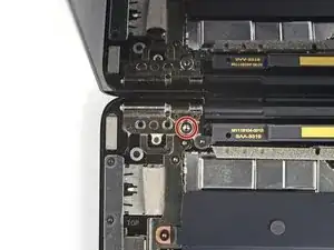
While holding the screen steady, use a T6 Torx driver to remove the four outermost 5.9 mm screws securing the screen, two on each side.
-
Leave the two innermost hinge screws in place for now, one on each side.
-
-
-
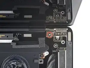
While holding the screen steady, use a T6 Torx driver to remove the two remaining 5.9 mm screws securing the screen, one on each side.
-
-
-
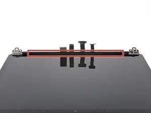
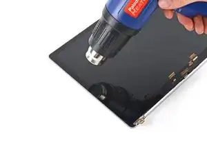
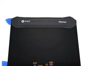
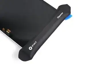
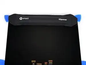
Apply a heated iOpener to the long plastic cable bracket at the base of your screen for one minute to soften its adhesive.
-
-
-
Insert an opening pick into the seam between the cable bracket and the LCD back cover, to the right of the cables.
-
Slide your pick toward the left hinge to separate the adhesive.
-
-
-
Insert your opening pick again to the left of the cables and slide it toward the hinge to fully separate the adhesive.
-
-
-
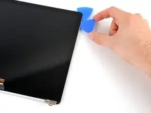
Grab the middle of the cable bracket and pull it away from the cables.
-
Pull the left side of the bracket out of its recess near the hinge.
-
-
-
The screen used in this guide has a smaller gap on the right side, which would be harder to start with.
-
The left edge has a wider gap, which would be easier to start with.
-
-
-
Note the location of the adhesive we're softening on this step: long strips secure each short edge of the screen.
-
Apply a heated iOpener to the left edge of the screen for three minutes.
-
-
-
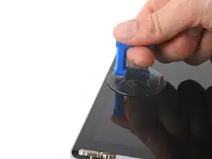
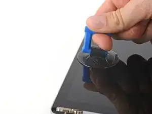
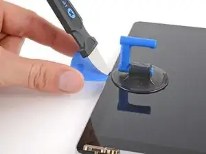
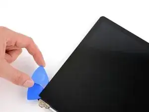
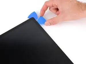
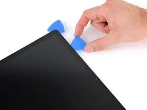
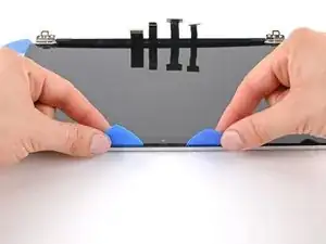
Place a suction handle on the left edge of the screen, as close to the edge as possible.
-
Pull up on the suction handle with a strong and steady force to slightly lift the glass.
-
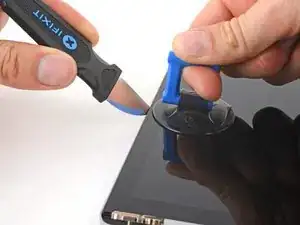
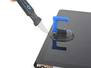
Insert a Jimmy, iFlex, or other thin metal tool at a 45-degree angle in the gap between the screen and back cover.
-
-
-
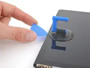
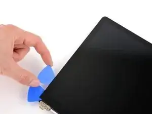
Slide your opening pick toward the hinge.
-
Leave your pick in the bottom left corner of the screen to prevent the adhesive from resealing.
-
-
-
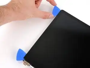
Insert a second opening pick next to the one in the bottom left corner.
-
Slide the pick to the top left corner to completely separate the left edge adhesive.
-
Leave this pick in the top left corner to prevent the adhesive from resealing.
-
-
-
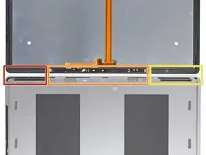
The left section of adhesive extends 69 mm (2.7 in) from the left edge of the screen and is 6 mm deep.
-
The middle section of adhesive is 2 mm deep. The sensors are held in a protective bracket adhered to the screen.
-
The right section of adhesive extends 84 mm (3.3 in) from the right edge of the screen and is 6 mm deep.
-
-
-
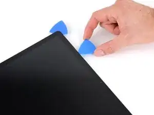
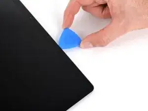
Insert a third opening pick next to the one in the top left corner.
-
Slide your pick toward the middle of the screen to separate the adhesive until you reach the sensor bracket, 69 mm (2.7 in) from the left edge.
-
-
-
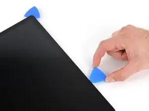
Slide your pick to the top right corner of the screen.
-
Leave this pick in the top right corner to prevent the adhesive from resealing.
-
-
-
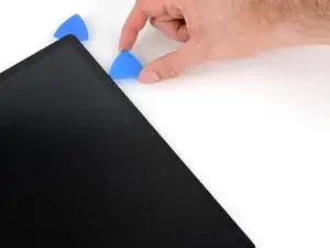
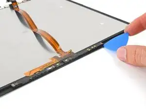
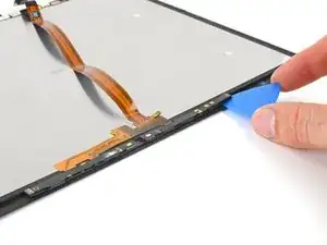
Insert a fourth opening pick next to the one in the top right corner.
-
Slide the pick to the bottom right corner to completely separate the right edge adhesive.
-
Leave this pick in the bottom right corner to prevent the adhesive from resealing.
-
-
-
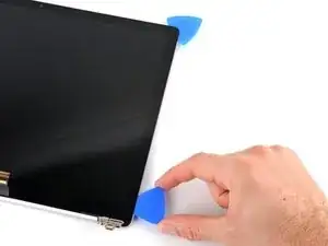
Rotate your screen so the top edge is closest to you.
-
Grab the two opening picks at the top corners of the screen and slide them toward the middle until they're stopped by the sensor bracket.
-
Angle both picks downward so they slide underneath the sensor bracket.
-
Slide the angled picks toward the middle of the screen until the top edge separates from the back cover.
-
-
-
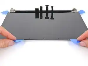
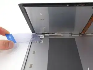
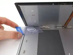
Hold your screen propped up with one hand.
-
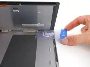
With your other hand, use a plastic card to slice the adhesive securing the bottom left and right corners.
-
-
-
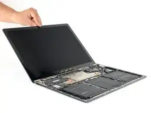
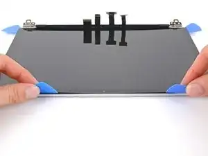
Grab the top corners of the screen and lower it back down flat onto the back cover.
-
Pull the screen away from the hinges and "walk" it side-to-side to separate the remaining adhesive along the bottom edge.
-
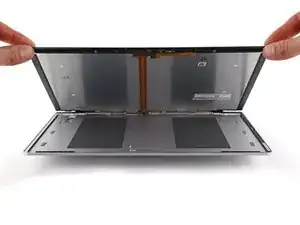
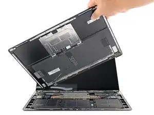
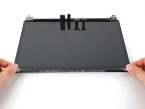
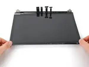
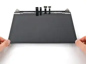
Remove the screen.
-
-
-
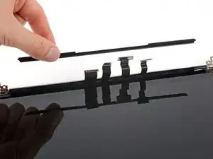
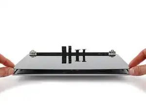
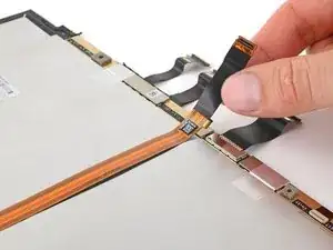
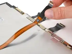
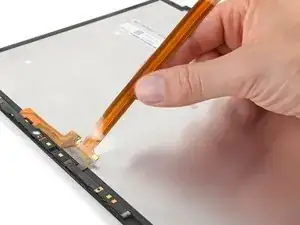
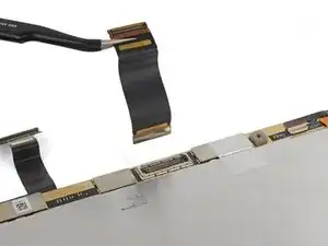
Flip the screen over and lay it glass-side down onto your work surface.
-
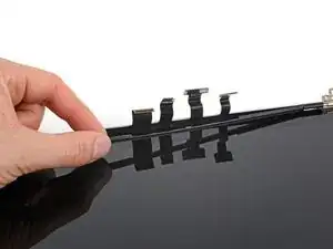
Gently peel up the long ribbon cable.
-
-
-
Apply a heated iOpener to the sensor bracket for one minute.
-
The left edge of the sensor bracket is 69 mm (2.7 in) from the edge of the screen.
-
The right edge of the sensor bracket is 84 mm (3.3 in) from the edge of the screen.
-
-
-
With the top edge of the screen closest to you, insert an opening pick under the right edge of the sensor bracket.
-
Slide your pick under the bracket to separate the adhesive.
-
-
-
Once you reach the end of the sensor bracket, rotate your opening pick around the left edge.
-
Slide your pick under the section of cable adhered to the screen to separate its adhesive.
-
-
-
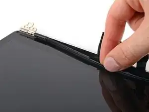
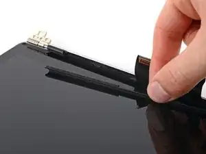
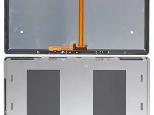
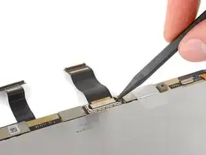
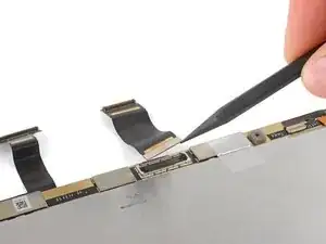
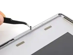
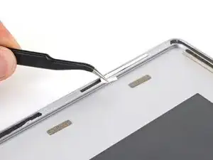
Use the point of your spudger to pry up and disconnect the short display cable from the screen.
-
Remove the cable.
-
-
-
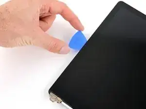
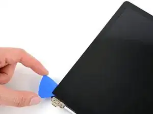
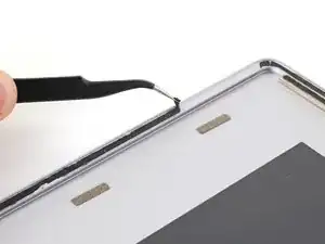
Use tweezers or your fingers to peel and remove any pieces of residual adhesive from the back cover.
-
Clean the perimeter of the back cover with isopropyl alcohol and a lint-free or microfiber cloth.
-
Apply strips of thin double-sided tape to the back cover in the same locations as the old adhesive.
-


Compare your new replacement part to the original part—you may need to transfer remaining components or remove adhesive backings from the new part before installing.
To reassemble your device, follow the above steps in reverse order.
Take your e-waste to an R2 or e-Stewards certified recycler.
Repair didn’t go as planned? Try some basic troubleshooting or search our Answers community for help.