Introduction
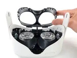
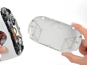
This guide shows how to remove and replace the screen and lens assembly for the Meta Quest 2.
The screen and lens assembly includes the lens housing, screen panels, lens optics, and motion tracking cameras.
Note: You'll need a long PH00 bit or a dedicated PH00 screwdriver to remove some recessed screws.
-
-
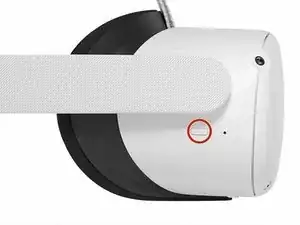
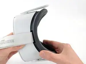
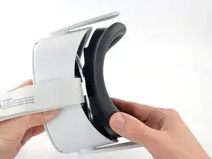
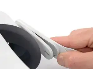
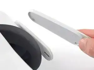
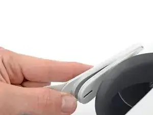
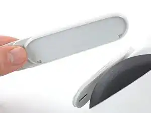
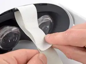
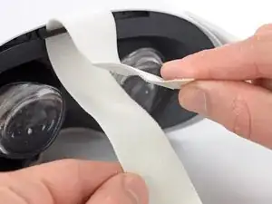
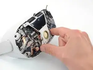
Use your fingers to grasp the right strap near the headset.
-
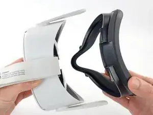
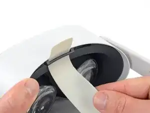
Peel the right strap away from the headset arm to unclip it.
-
-
-
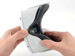
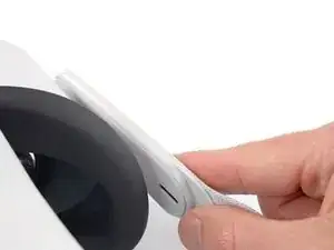
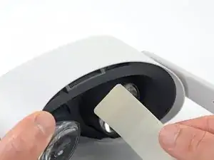
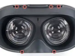
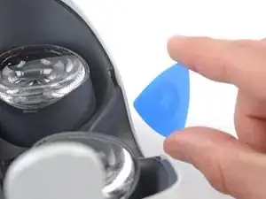
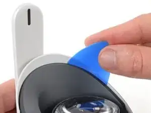
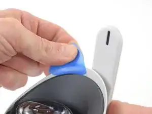
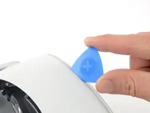
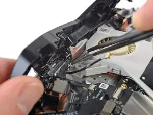
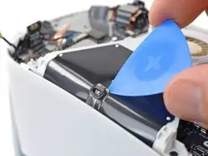
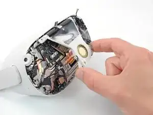
Insert an opening pick into the seam between the eyepiece trim and white outer shell, near the nose cutout.
-
-
-
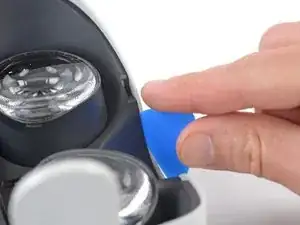
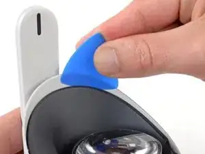
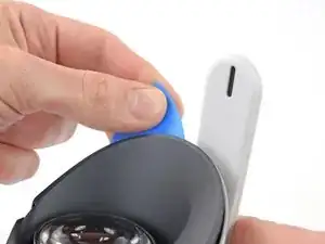
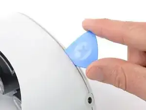
Slide the opening pick to the right along the seam to release the clips securing the eyepiece trim.
-
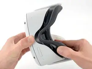
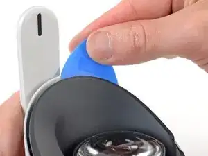
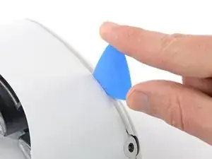
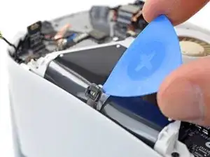
Pry with the opening pick to release the clips securing the right side of the eyepiece trim.
-
Leave the opening pick in the seam to prevent the clips from reengaging.
-
-
-
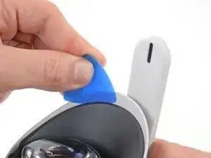
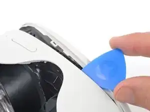
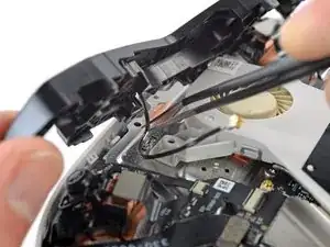
Repeat the prying procedure along the left edge to release the clips securing the eyepiece trim.
-
-
-
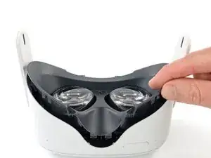
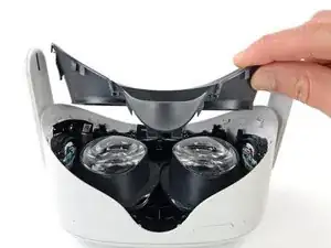
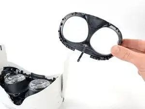
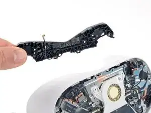
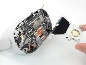
Lift the eyepiece trim slightly and tilt it towards the top edge of the headset.
-
Set the trim down on your work surface, making sure not to strain the cable.
-
-
-
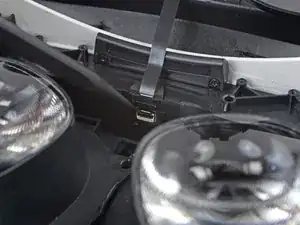
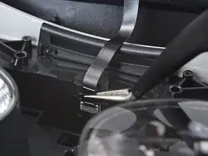
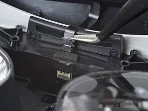
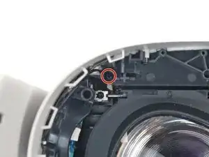
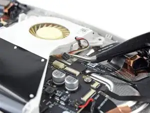
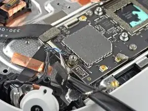
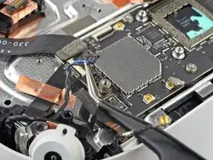
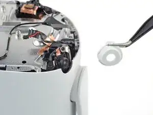
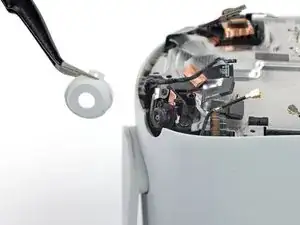
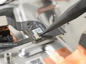
Use the point of a spudger to flip open the black lock tab on the ZIF connector securing the face sensor cable.
-
-
-
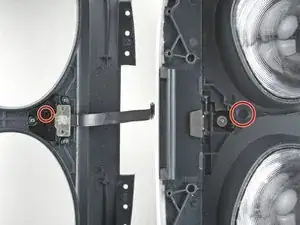
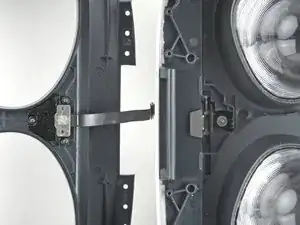
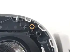
Make sure the lens spacing matches the spacing indicator. This allows the indicator peg to sit correctly in its notch.
-
If the lens spacing doesn't match the indicator, manually adjust the lens with your fingers.
-
-
-
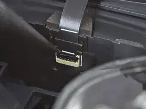
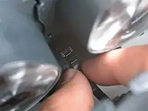
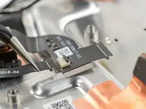
Thread your fingers through the eyepiece trim’s eyeholes and grasp the edges of the sensor cable.
-
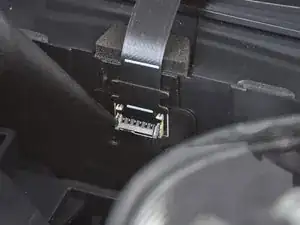
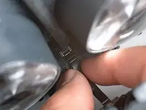
Slide the sensor cable into the socket until the first set of tabs rests in the socket. This should flip the lock tab down partially.
-
Use a spudger to press the lock tab down towards the cable to lock it in place.
-
-
-
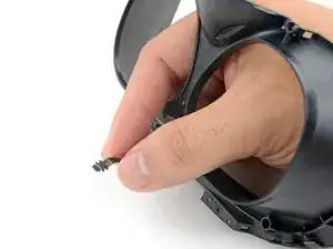
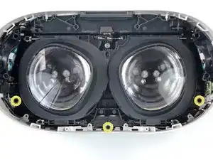
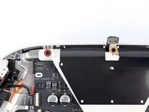
Use a Phillips screwdriver to remove the five 7.7 mm‑long screws securing the front cover to the headset:
-
One recessed in the top-left corner
-
One recessed in the top-right corner
-
Three along the lower edge
-
-
-
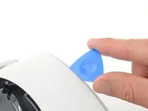
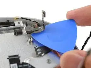
Insert an opening pick into the seam between the bottom edge of the front cover and the headset.
-
Pry with the opening pick to release the front cover clips.
-
-
-
Slide the opening clip along the seam and pry to release all the clips securing the front cover.
-
-
-
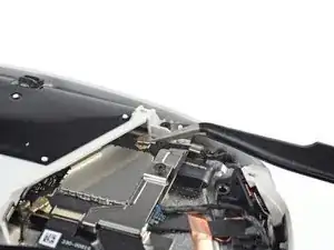
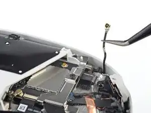
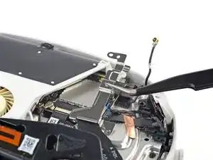
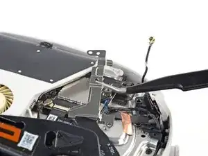
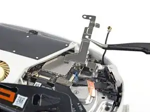
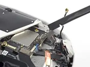
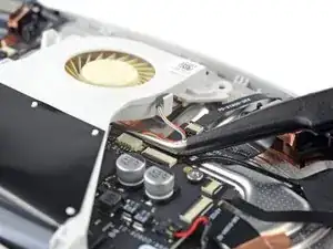
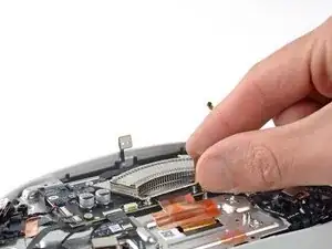
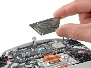
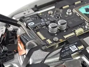
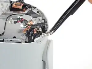
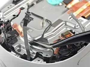
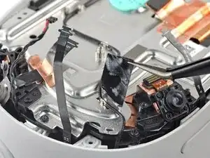
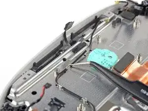
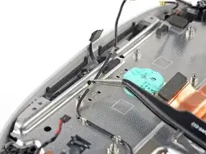
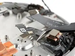
Use a pair of tweezers to grasp the metal neck of the top-right antenna cable.
-
Lift the antenna connector straight up to disconnect it.
-
Guide the antenna cable out of its metal clip holding it in place.
-
-
-
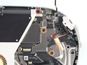
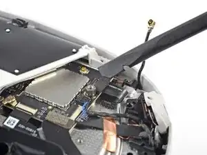
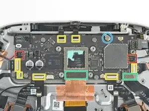
Use a Phillips screwdriver to remove the three screws securing the battery cable bracket:
-
One 4.4 mm‑long screw
-
Two 2.3 mm‑long screws
-
-
-
Use tweezers or your fingers to grasp the battery cable bracket.
-
Twist the cable bracket slightly so that its bottom left corner unclips from the motherboard.
-
Remove the battery cable bracket.
-
-
-
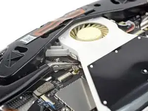
Use a Phillips screwdriver to remove the eight screws securing the antenna assembly to the headset:
-
Four 4.4 mm‑long screws
-
Two 4.8 mm‑long screws
-
Two 10.7 mm‑long screws
-
-
-
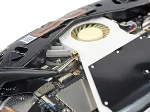
Use the point of an opening pick to loosen the adhesive securing the LED flex cable from the top of the fan assembly.
-
-
-
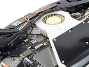
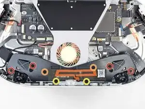
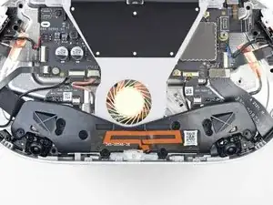
Remove the two screws securing the fan assembly to the headset:
-
One 4.4 mm‑long Phillips screw
-
One 3.6 mm‑long Torx T2 screw
-
-
-
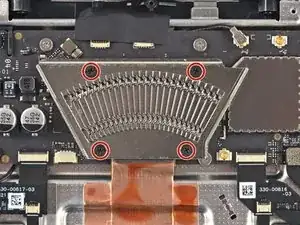
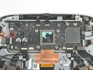
Use a Phillips screwdriver to remove the four 2.3 mm‑long screws securing the heat sink to the motherboard.
-
-
-
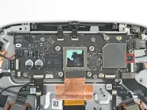
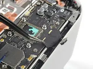
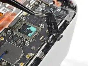
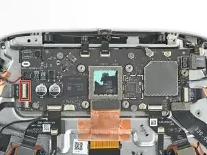
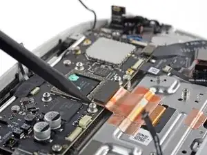
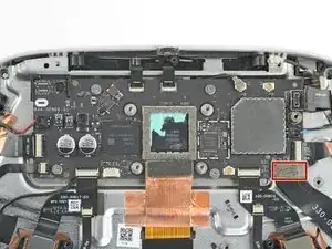
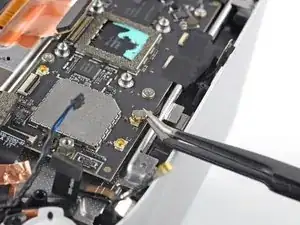
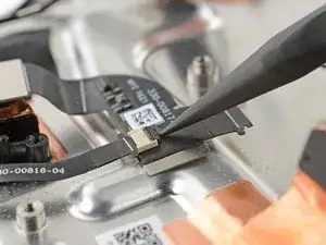
Use a clean fingernail or a spudger to pry up the lock tab securing the top left camera cable.
-
-
-
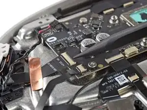
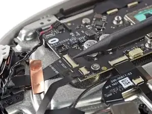
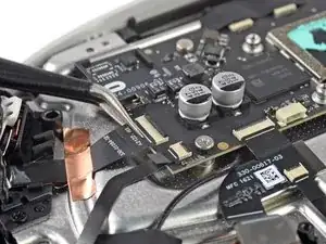
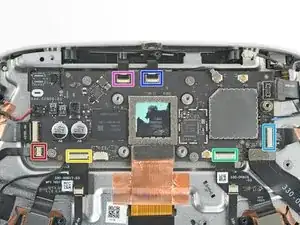
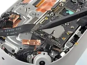
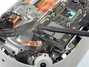
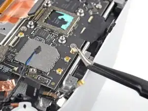
Move counter-clockwise around the motherboard and disconnect the remaining six ZIF connectors:
-
Power button and LED board
-
Bottom left camera
-
Bottom right camera
-
Top right camera
-
Face sensor interconnect cable
-
Indicator LED cable
-
-
-
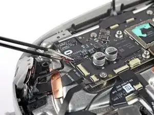
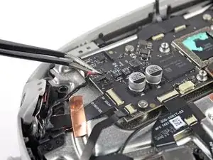
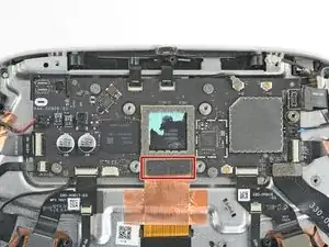
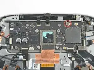
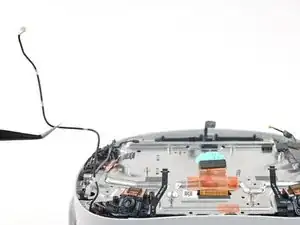
Insert one arm of a pair of tweezers under the metal neck of the side antenna cable.
-
Lift the antenna connector straight up to disconnect it.
-
-
-
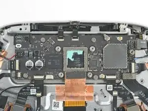
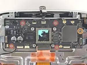
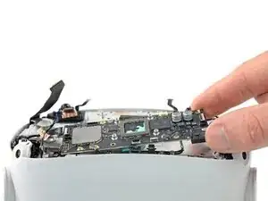
Remove the five screws securing the motherboard to the headset:
-
Four 3.8 mm‑long Phillips screws
-
One 6 mm‑long 3.5 mm hex standoff screw
-
-
-
Use a spudger to pry up the black lock tab securing the left microphone flex cable to the left interconnect cable.
-
Use your fingers or tweezers to slide the microphone cable out of the ZIF connector.
-
-
-
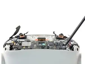
Slide the point of an opening pick underneath the battery flex cable to loosen the adhesive securing it from the headset.
-
-
-
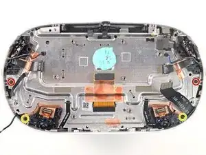
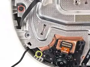
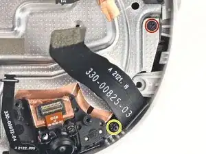
Use a Phillips screwdriver to remove the four screws securing the screen and lens assembly to the frame:
-
Two 6.5 mm‑long screws
-
Two 7.7 mm‑long screws
-
-
-
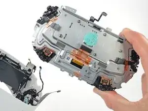
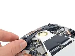
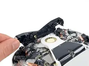
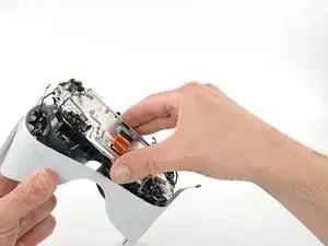
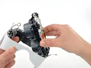
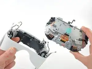
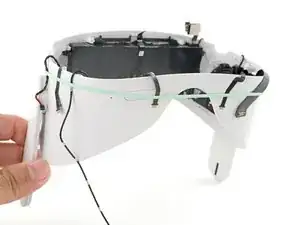
Grasp the screen and lens assembly with your fingers.
-
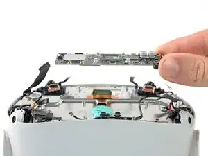
Slowly lift and separate the assembly from the outer shell, taking care to reposition any cables that get in the way.
-
Remove the screen and lens assembly.
-
-
-
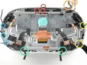
Three cables along the top edge—two flex cables and one LED flex cable
-
Two cables in the top right corner—the battery connector and an antenna cable
-
Two cables along the right edge—an antenna cable and a wide flex cable
-
Two flex cables along the bottom edge
-
Three cables along the left edge—one antenna cable, one flex cable, and one speaker cable
-


To reassemble your device, follow these instructions in reverse order.
Take your e-waste to an R2 or e-Stewards certified recycler.
Repair didn’t go as planned? Try some basic troubleshooting, or ask our Answers community for help.

4 comments
안녕하세요~
Meta Quest 2에 단열소재가 적용되어 있는지 문의 드립니다.
단열소재가 있다면 어느정도의 size인지 알고 싶습니다.
답변 부탁 드립니다.
박성철 -
I had mine outside for less then a minute and i had a long yellow line Across the screen and i know it would be cheaper to fix it yourself and you having a step by step instructions on how to fix it is the absolute best thing i have seen a console developer do so you doing this probably super helpful to so many people Thank you
If it doesn’t bother you too much, wait until you need to fix something else(i. e. the battery) and replace the screen with it. If it is a big line, then consider replacing it.
Hello, i need to replace my lcd 'cause sun burned it, whats the name of the "glue" that holds the lcd to his frame?