Introduction

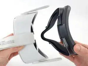
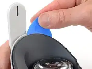
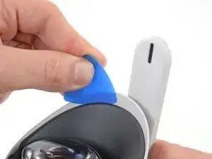
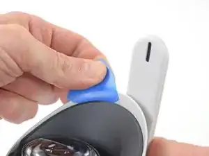
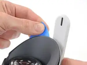
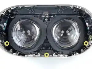
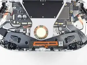
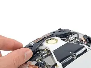
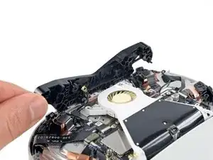
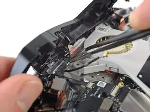
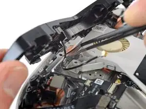
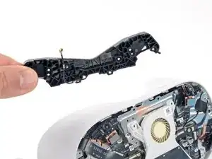
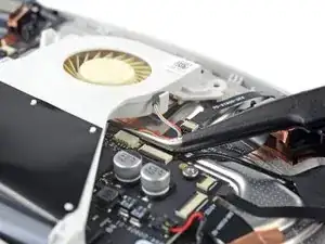
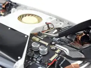
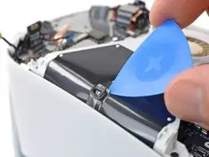
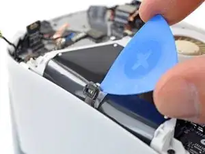
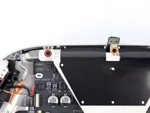
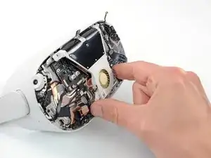
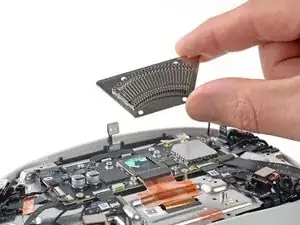
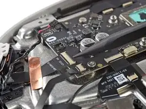
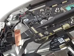
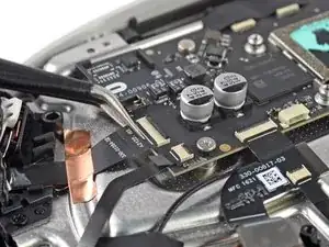
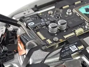
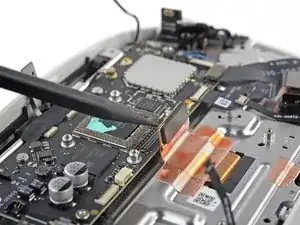
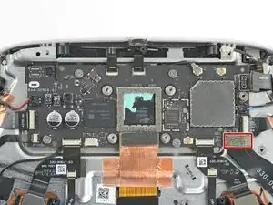
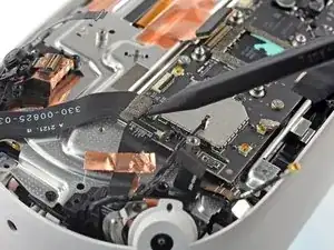
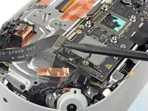
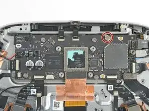
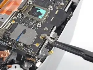
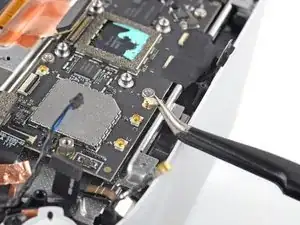
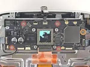
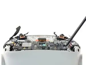
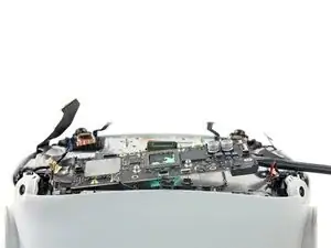
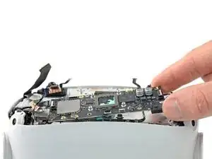
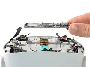
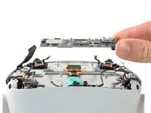
This guide shows how to remove and replace the motherboard for your Meta Quest 2.

Note: You'll need a long PH00 bit or a dedicated PH00 screwdriver to remove some recessed screws.

  1. SqbHLQOA2SemeF4D
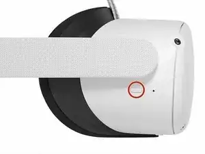
    • Hold the power button for three seconds to fully turn off your headset.

    • You'll hear a power down chime, and the LED next to the power button will turn off.

  2. B31djmGYZZHCBoti
    B31djmGYZZHCBoti
    OEu2hrgBLV4wSLKR
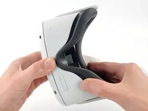
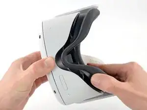
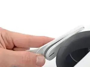
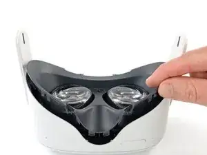
    • Grasp and pull on the nose section of the facial interface to unclip it from the headset.

    Photos of each step and interim made this guide so easy to follow.

    For.The.Tech.Of.It -

  3. Be2J2NaNLeqZuRhi
    Be2J2NaNLeqZuRhi
    BFoGtcvupgIvCQIK
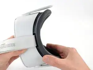
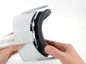
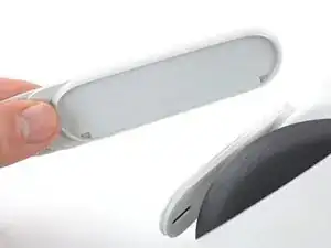
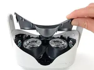
    • Grasp and pull on the top section of the facial interface to unclip it from the headset.

  4. uLFjxFFQlhXdWAtB
    • Remove the facial interface.

    • During reassembly, align the facial interface to the headset and use your fingers to press along the perimeter to clip it back in.

  5. URh1oymFaf6RLYSM
    URh1oymFaf6RLYSM
    yHfWoon1NiqXGyYB
    CDnYbnLkUxyibGsY
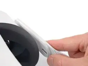
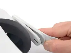
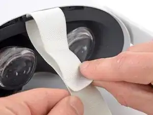
    • Use your fingers to grasp the right strap near the headset.

    • Peel the right strap away from the headset arm to unclip it.

  6. 4nENMVhqOjgOunbA
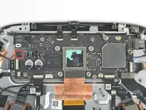
    4nENMVhqOjgOunbA
    Moo6ThGGPZGnMGZV
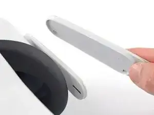
    • Repeat the procedure to peel the left strap away from the arm to unclip it.

  7. hSyfJboRQGTssgOk
    hSyfJboRQGTssgOk
    t5EGhNgdrvxuoPHu
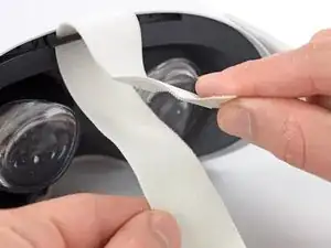
    • Separate the hook and loop strip on the top strap.

  8. wquuIQnnECAaTkt2
    wquuIQnnECAaTkt2
    JVJruOK5jI2NowDF
    • Unthread the top strap from its bracket.

    • Remove the head strap.

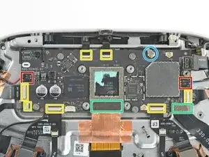
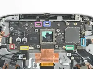
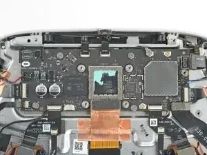
  9. yPeQSMKFUNr1DPW5
    yPeQSMKFUNr1DPW5
    wRjMBK6TWEpLYbBA
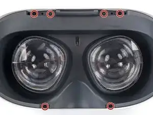
    • Use a Torx T2 driver to remove the six 3.5 mm‑long screws securing the eyepiece trim.

  10. awTJYMHOLskpVy4a
    awTJYMHOLskpVy4a
    KWMNHLbd5KelgGYP
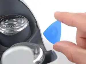
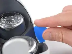
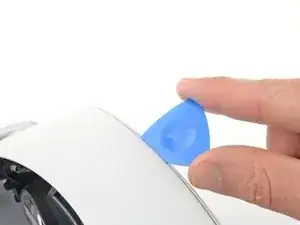
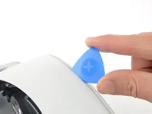
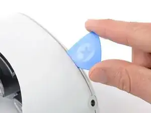
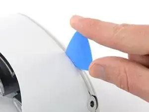
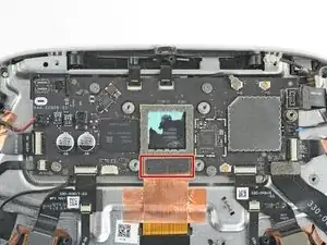
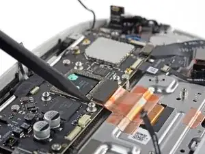
    • Insert an opening pick into the seam between the eyepiece trim and white outer shell, near the nose cutout.

  11. ryWGlBHZ6TRrA2q3
    ryWGlBHZ6TRrA2q3
    AZiweYguFJHZQQJu
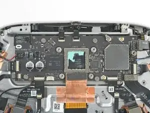
    MaqaHyaOdJr2NIML
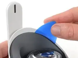
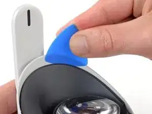
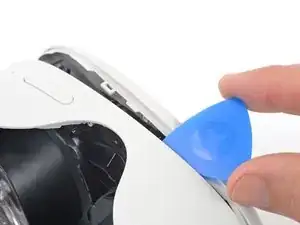
    • Slide the opening pick to the right along the seam to release the clips securing the eyepiece trim.

    • Pry with the opening pick to release the clips securing the right side of the eyepiece trim.

    • Leave the opening pick in the seam to prevent the clips from reengaging.

  12. Sa24OOHFX6N4vDmB
    Sa24OOHFX6N4vDmB
    3iNTLEdaGtMhjiyk
    pu63GssAMaSOmugP
    • Repeat the prying procedure along the left edge to release the clips securing the eyepiece trim.

    • During reassembly, press your fingers along the perimeter of the eyepiece trim to clip it back in place.

  13. 6UjuCJF2TSnIAy4n
    6UjuCJF2TSnIAy4n
    IKRAfAuj4VCBFKUD
    oW4opLiLOo6DACSH
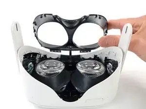
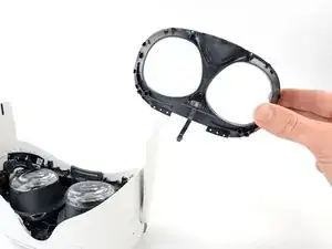
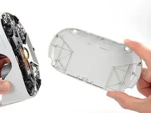
    • Don’t try to fully remove the eyepiece trim in this step. It’s still connected to the headset by a short cable.

    • Lift the eyepiece trim slightly and tilt it towards the top edge of the headset.

    • Set the trim down on your work surface, making sure not to strain the cable.

  14. IDPgUcSVOPIEsjVV
    IDPgUcSVOPIEsjVV
    5u5lQh6PJ2chJBwb
    lj1QMH44RFNZEuRQ
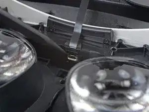
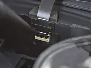
    • Use the point of a spudger to flip open the black lock tab on the ZIF connector securing the face sensor cable.

  15. HJpDCNb5JfYwxOIJ
    HJpDCNb5JfYwxOIJ
    jZnsVTqBDoUbP5lG
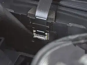
    • Use tweezers to pull the face sensor cable out of the ZIF connector.

  16. LMhTeOsbLDb1XMV5
    • Remove the eyepiece trim.

  17. eeARhGrBQQX4Svh6
    eeARhGrBQQX4Svh6
    fVmHwAqUICN2xLEh
    • During reassembly:

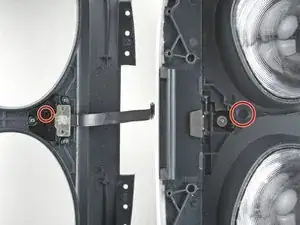
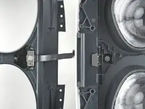
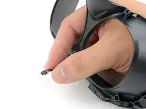
    • Make sure the lens spacing matches the spacing indicator. This allows the indicator peg to sit correctly in its notch.

    • If the lens spacing doesn't match the indicator, manually adjust the lens with your fingers.

  18. ieFjqZM1WWktjJba
    ieFjqZM1WWktjJba
    XPwf1y2hpXquo2Y6
    6ASSdjFCu4I2QxSu
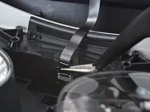
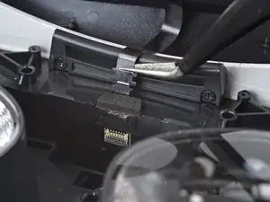
    • During reassembly, the face sensor cable can be tricky to connect. Follow these tips to connect the cable:

    • Thread your fingers through the eyepiece trim’s eyeholes and grasp the edges of the sensor cable.

    • Slide the sensor cable into the socket until the first set of tabs rests in the socket. This should flip the lock tab down partially.

    • Use a spudger to press the lock tab down towards the cable to lock it in place.

  19. bIZDy5CHBbcqjpJS
    bIZDy5CHBbcqjpJS
    aWkWNiGRlSfIsovH
    ycivRaY5eoMCyKPR
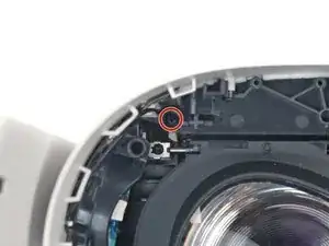
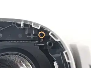
    • Use a Phillips screwdriver to remove the five 7.7 mm‑long screws securing the front cover to the headset:

    • One recessed in the top-left corner

    • One recessed in the top-right corner

    • Three along the lower edge

  20. xWRgqZ1JgWRlykWW
    xWRgqZ1JgWRlykWW
    WrousOOOoDosqXvU
    • The front cover is still held in place by clips along the bottom and side edges.

    • Insert an opening pick into the seam between the bottom edge of the front cover and the headset.

    • Pry with the opening pick to release the front cover clips.

  21. 3LnvxKG2jsGVCSgK
    3LnvxKG2jsGVCSgK
    gB5eYUFcG2kVKtTy
    Md143WrILgHS3d2T
    • Slide the opening clip along the seam and pry to release all the clips securing the front cover.

  22. h1lljSnlo4ryN2NH
    • Remove the front cover.

  23. 1niLgPNKCs3Q2RYO
    1niLgPNKCs3Q2RYO
    ZQTRDvgfr1bQCUTT
    rbbRR1xsuyOVjPAT
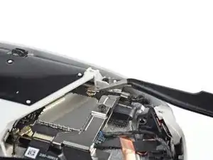
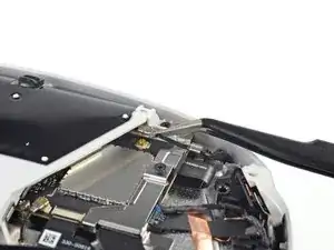
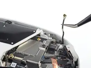
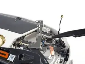
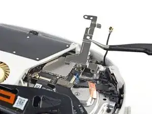
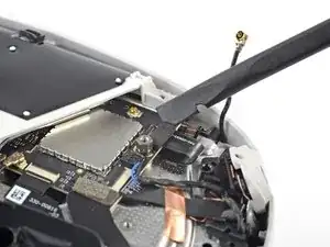
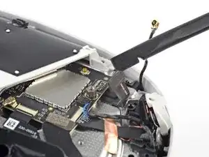
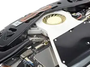
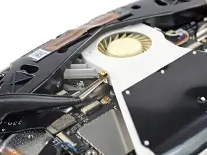
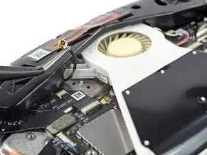
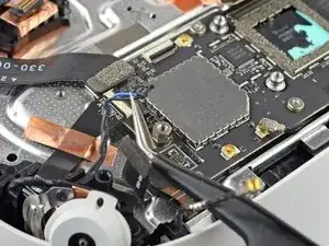
    • Use a pair of tweezers to grasp the metal neck of the top-right antenna cable.

    • Lift the antenna connector straight up to disconnect it.

    • Guide the antenna cable out of its metal clip holding it in place.

  24. rrf1SRZ5CTAJMCXR
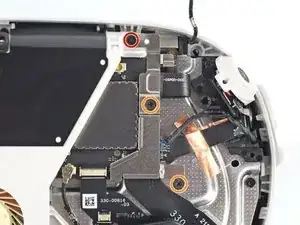
    • Use a Phillips screwdriver to remove the three screws securing the battery cable bracket:

    • One 4.4 mm‑long screw

    • Two 2.3 mm‑long screws

  25. RLKP44dc5MyLNE4c
    RLKP44dc5MyLNE4c
    keO2L1NjZ2GoxS4Q
    Aau6lETkm3TyjOXe
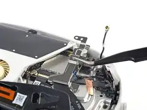
    • Use tweezers or your fingers to grasp the battery cable bracket.

    • Twist the cable bracket slightly so that its bottom left corner unclips from the motherboard.

    • Remove the battery cable bracket.

  26. EqZBNkYNujVkJoDg
    EqZBNkYNujVkJoDg
    423XfyDCcNOYIcqf
    • Use a spudger to pry up and disconnect the battery press connector from the motherboard.

    • The battery press connector can disconnect accidentally during reassembly. Check this connector before you attach the bracket.

  27. nFmJVJ5cyPviepP4
    nFmJVJ5cyPviepP4
    S3BSRDImvyJyOAa6
    fx3AcDgfXifTufph
    • Insert one arm of a pair of tweezers under the metal neck of the black antenna cable near the fan assembly.

    • Lift the antenna connector straight up to disconnect it.

    • Guide the antenna cable out of its metal clip holding it in place.

  28. 1vVKPlQSdrClHZSr
    1vVKPlQSdrClHZSr
    ajhNCUNButeFOfyj
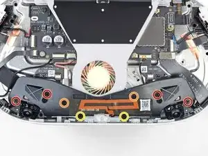
    • Use a Phillips screwdriver to remove the eight screws securing the antenna assembly to the headset:

    • Four 4.4 mm‑long screws

    • Two 4.8 mm‑long screws

    • Two 10.7 mm‑long screws

    I love the way you color-coded each set of screws to help with organization!

    For.The.Tech.Of.It -

  29. Lw3smC1QVWMYAJJg
    Lw3smC1QVWMYAJJg
    UcM6ClRodHFelFv6
    • Use your fingers to flip up the antenna assembly enough to access the cable underneath it.

  30. 6LY6OiglnJgFAnge
    6LY6OiglnJgFAnge
    K2EwCeyJvVVYpcCn
    • Use tweezers to unclip the antenna cable from its metal clip.

  31. xKTviVUmYCPnGWVW
    • Remove the front antenna assembly.

  32. mCebBB4cGIPqoKGy
    mCebBB4cGIPqoKGy
    K3IpvieYdIaOOdBW
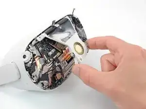
    • Use tweezers to grab the fan connector and carefully slide it out of its socket.

  33. DWZWNQy4B3VLaLNN
    DWZWNQy4B3VLaLNN
    DrjZD3ixHuO3LIv6
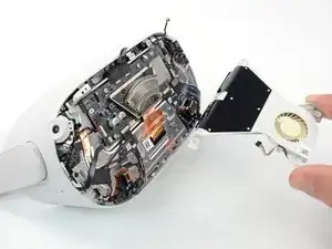
    • Use the point of an opening pick to loosen the adhesive securing the LED flex cable from the top of the fan assembly.

  34. 5yujPEdVZWUxeumi
    • Remove the two screws securing the fan assembly to the headset:

    • One 4.4 mm‑long Phillips screw

    • One 3.6 mm‑long Torx T2 screw

  35. ZDW1pxVQcoJrFjCa
    ZDW1pxVQcoJrFjCa
    GUCJpYyCjjEWJjGb
    Y1QU4I1mmx2pLqII
    • Lift the fan assembly and remove it.

  36. vLWyVTsSQrvtpt3s
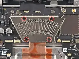
    • Use a Phillips screwdriver to remove the four 2.3 mm‑long screws securing the heat sink to the motherboard.

  37. MZOYFv2isvtgaW1Z
    MZOYFv2isvtgaW1Z
    4SjJPBtsYgiGWWGy
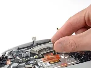
    • Use your fingers to lift the heat sink and remove it.

    • You may feel a bit of resistance. This is normal since the midframe is slightly bonded to the heat sink with thermal paste.

    • You can reuse the thermal paste if you keep it clean. Otherwise, use a spudger to scrape off the old paste and apply a small amount of viscous thermal compound (such as K5 Pro) to the processor.

  38. DZyklxLpX3YLAgkT
    DZyklxLpX3YLAgkT
    RB1FjHdeEDaN4HnX
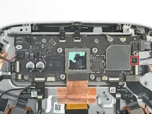
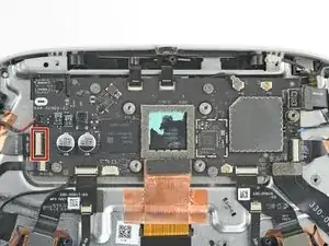
    • During reassembly, stop here and check if these twelve connectors are properly connected to the motherboard:

    • Two speaker connectors

    • Seven ZIF connectors

    • Two press connectors

    • One antenna connector

    • There are additional connectors on the motherboard, but they shouldn't be connected at this point.

  39. wKSRFH2BpkekHG4g
    wKSRFH2BpkekHG4g
    irMqp4POPG4ILXUX
    LWC1HwRQM3ettGHt
    • Use tweezers to grip the left speaker cables at the base of their motherboard connector.

    • Lift the connector gently straight up to disconnect it.

    • During reassembly, use the flat end of a spudger to press the speaker cable into the rubber holding clip.

  40. UVZTJgQYRuIEVbJk
    UVZTJgQYRuIEVbJk
    EyRPTr2F26BdGUm6
    r2qAKOVUpAxrWFpL
    • Repeat the disconnection procedure for the right speaker connector.

    • During reassembly, use the flat end of a spudger to press the speaker cable into the rubber holding clip.

  41. 3VJpbAHUM1UTNFaT
    3VJpbAHUM1UTNFaT
    hqSGxvNAOlFHkAIm
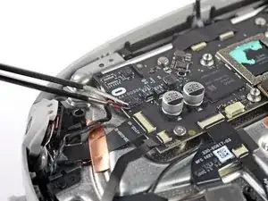
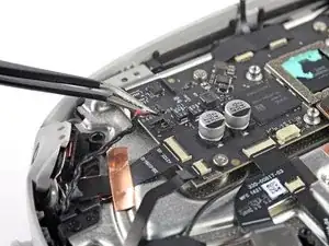
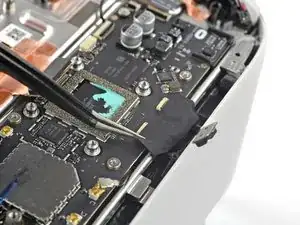
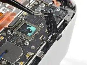
    • Use tweezers to gently peel the black tape covering the two top flex cables.

    • Set the tape aside to be reused during reassembly.

  42. KOUHCCAxCQhPffnI
    KOUHCCAxCQhPffnI
    3AVlef6nlAsbZK5f
    Ljffb2dQRjMxgqAA
    • Use a clean fingernail or a spudger to pry up the lock tab securing the top left camera cable.

  43. fUQkLCfZtu6lPcFE
    fUQkLCfZtu6lPcFE
    dBN12YNbBPOoDUCl
    • Grasp the top left camera cable with tweezers and slide it out of its ZIF connector.

  44. Osj4I1booHmc2Gqn
    Osj4I1booHmc2Gqn
    gZfBYEMJFiDDtkcx
    • Move counter-clockwise around the motherboard and disconnect the remaining six ZIF connectors:

    • Power button and LED board

    • Bottom left camera

    • Bottom right camera

    • Top right camera

    • Face sensor interconnect cable

    • Indicator LED cable

  45. RR5INVeWHakaxnaI
    RR5INVeWHakaxnaI
    dDl61uxkE66UHqyD
    UjSqiJXA4RiOYvof
    • Use a spudger to pry up and disconnect the display cable.

  46. anPQNrwnxXOYDdTK
    anPQNrwnxXOYDdTK
    d2XbQCKY1mTqwvOs
    UnAiEXNZuKgIJSJK
    • Use a spudger to pry up and disconnect the USB‑C and headphone jack cable.

  47. fd3DZaRVdP6XrVXc
    fd3DZaRVdP6XrVXc
    VOjloIQRueniA6lD
    mXmhNvDB22153SqU
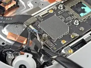
    • Insert one arm of a pair of tweezers under the metal neck of the side antenna cable.

    • Lift the antenna connector straight up to disconnect it.

  48. XnGLrWIcG6E1pykJ
    • Remove the five screws securing the motherboard to the headset:

    • Four 3.8 mm‑long Phillips screws

    • One 6 mm‑long 3.5 mm hex standoff screw

    hex and left down screw with washer

    k i -

  49. 1AoQCT5veJJ3XhQm
    1AoQCT5veJJ3XhQm
    rGFYYcC1rtqIchFd
    • At this point, the motherboard should be loose, with some thermal paste sticking it to the headset.

    • Use a spudger to pry up and separate the motherboard from the headset.

    • If it feels like the motherboard is caught on something, check that all the cables are disconnected from it.

  50. trHbOB6jGmMo2Npu
    trHbOB6jGmMo2Npu
    OYArJ1JaGFeMCK1J
    • Remove the motherboard.

    • You can reuse the thermal paste if you keep it clean. Otherwise, use a spudger to scrape off the old paste and apply a small amount of viscous thermal compound (such as K5 Pro) to the processor.

Conclusion

To reassemble your device, follow these instructions in reverse order.

Take your e-waste to an R2 or e-Stewards certified recycler.

Repair didn’t go as planned? Try some basic troubleshooting, or ask our Answers community for help.
Arthur Shi

Member since: 03/01/18

272294 Reputation

0 comments