Introduction

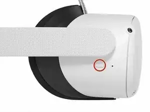
This guide shows how to remove and replace the front cover (aka front shell or faceplate) for your Meta Quest 2.

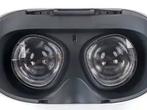
The front cover is the white plastic piece that covers the front of the headset. Removing the cover gives access to the motherboard.

Note: You'll need a long PH00 bit or a dedicated PH00 screwdriver to remove some recessed screws.

  1. SqbHLQOA2SemeF4D
    • Hold the power button for three seconds to fully turn off your headset.

    • You'll hear a power down chime, and the LED next to the power button will turn off.

  2. B31djmGYZZHCBoti
    B31djmGYZZHCBoti
    OEu2hrgBLV4wSLKR
    • Grasp and pull on the nose section of the facial interface to unclip it from the headset.

    Photos of each step and interim made this guide so easy to follow.

    For.The.Tech.Of.It -

  3. Be2J2NaNLeqZuRhi
    Be2J2NaNLeqZuRhi
    BFoGtcvupgIvCQIK
    • Grasp and pull on the top section of the facial interface to unclip it from the headset.

  4. uLFjxFFQlhXdWAtB
    • Remove the facial interface.

    • During reassembly, align the facial interface to the headset and use your fingers to press along the perimeter to clip it back in.

  5. URh1oymFaf6RLYSM
    URh1oymFaf6RLYSM
    yHfWoon1NiqXGyYB
    CDnYbnLkUxyibGsY
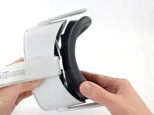
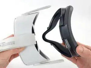
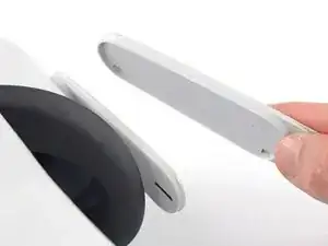
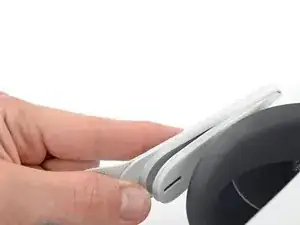
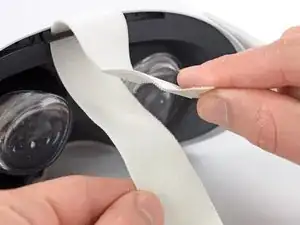
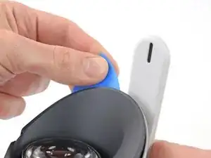
    • Use your fingers to grasp the right strap near the headset.

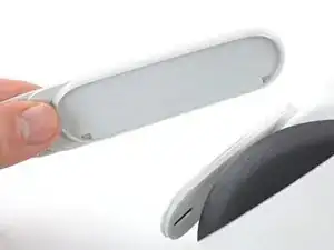
    • Peel the right strap away from the headset arm to unclip it.

  6. 4nENMVhqOjgOunbA
    4nENMVhqOjgOunbA
    Moo6ThGGPZGnMGZV
    • Repeat the procedure to peel the left strap away from the arm to unclip it.

  7. hSyfJboRQGTssgOk
    hSyfJboRQGTssgOk
    t5EGhNgdrvxuoPHu
    • Separate the hook and loop strip on the top strap.

  8. wquuIQnnECAaTkt2
    wquuIQnnECAaTkt2
    JVJruOK5jI2NowDF
    • Unthread the top strap from its bracket.

    • Remove the head strap.

  9. yPeQSMKFUNr1DPW5
    yPeQSMKFUNr1DPW5
    wRjMBK6TWEpLYbBA
    • Use a Torx T2 driver to remove the six 3.5 mm‑long screws securing the eyepiece trim.

  10. awTJYMHOLskpVy4a
    awTJYMHOLskpVy4a
    KWMNHLbd5KelgGYP
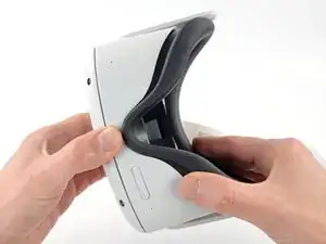
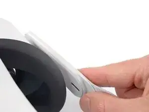
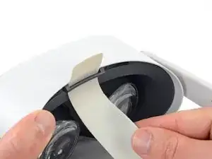
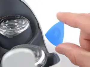
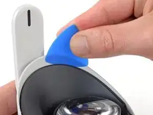
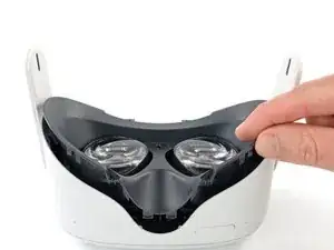
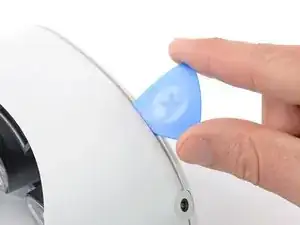
    • Insert an opening pick into the seam between the eyepiece trim and white outer shell, near the nose cutout.

  11. ryWGlBHZ6TRrA2q3
    ryWGlBHZ6TRrA2q3
    AZiweYguFJHZQQJu
    MaqaHyaOdJr2NIML
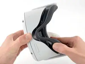
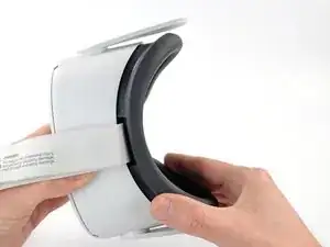
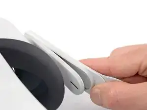
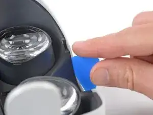
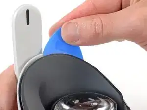
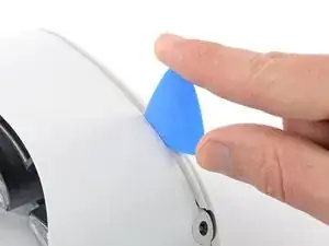
    • Slide the opening pick to the right along the seam to release the clips securing the eyepiece trim.

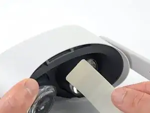
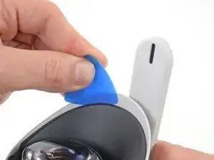
    • Pry with the opening pick to release the clips securing the right side of the eyepiece trim.

    • Leave the opening pick in the seam to prevent the clips from reengaging.

  12. Sa24OOHFX6N4vDmB
    Sa24OOHFX6N4vDmB
    3iNTLEdaGtMhjiyk
    pu63GssAMaSOmugP
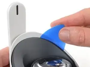
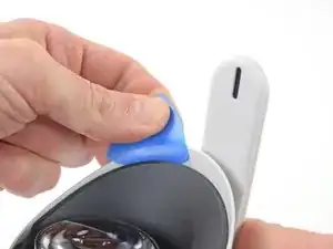
    • Repeat the prying procedure along the left edge to release the clips securing the eyepiece trim.

    • During reassembly, press your fingers along the perimeter of the eyepiece trim to clip it back in place.

  13. 6UjuCJF2TSnIAy4n
    6UjuCJF2TSnIAy4n
    IKRAfAuj4VCBFKUD
    oW4opLiLOo6DACSH
    • Don’t try to fully remove the eyepiece trim in this step. It’s still connected to the headset by a short cable.

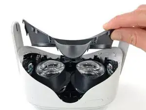
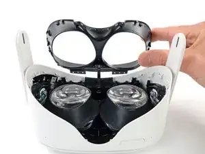
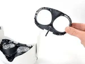
    • Lift the eyepiece trim slightly and tilt it towards the top edge of the headset.

    • Set the trim down on your work surface, making sure not to strain the cable.

  14. IDPgUcSVOPIEsjVV
    IDPgUcSVOPIEsjVV
    5u5lQh6PJ2chJBwb
    lj1QMH44RFNZEuRQ
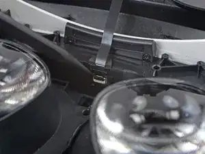
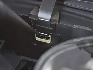
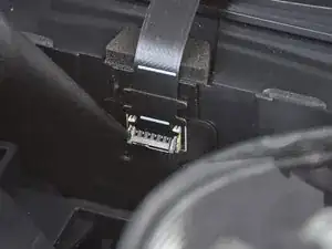
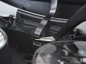
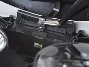
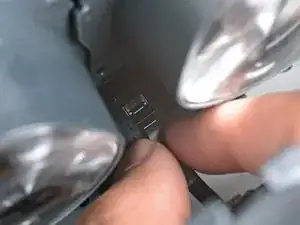
    • Use the point of a spudger to flip open the black lock tab on the ZIF connector securing the face sensor cable.

  15. HJpDCNb5JfYwxOIJ
    HJpDCNb5JfYwxOIJ
    jZnsVTqBDoUbP5lG
    • Use tweezers to pull the face sensor cable out of the ZIF connector.

  16. LMhTeOsbLDb1XMV5
    • Remove the eyepiece trim.

  17. eeARhGrBQQX4Svh6
    eeARhGrBQQX4Svh6
    fVmHwAqUICN2xLEh
    • During reassembly:

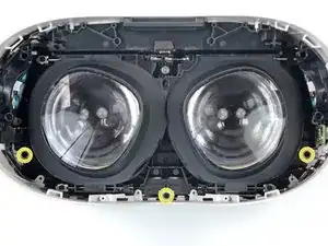
    • Make sure the lens spacing matches the spacing indicator. This allows the indicator peg to sit correctly in its notch.

    • If the lens spacing doesn't match the indicator, manually adjust the lens with your fingers.

  18. ieFjqZM1WWktjJba
    ieFjqZM1WWktjJba
    XPwf1y2hpXquo2Y6
    6ASSdjFCu4I2QxSu
    • During reassembly, the face sensor cable can be tricky to connect. Follow these tips to connect the cable:

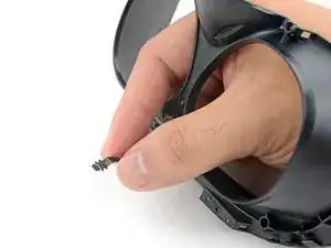
    • Thread your fingers through the eyepiece trim’s eyeholes and grasp the edges of the sensor cable.

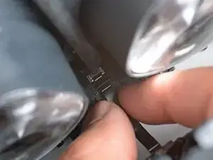
    • Slide the sensor cable into the socket until the first set of tabs rests in the socket. This should flip the lock tab down partially.

    • Use a spudger to press the lock tab down towards the cable to lock it in place.

  19. bIZDy5CHBbcqjpJS
    bIZDy5CHBbcqjpJS
    aWkWNiGRlSfIsovH
    ycivRaY5eoMCyKPR
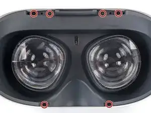
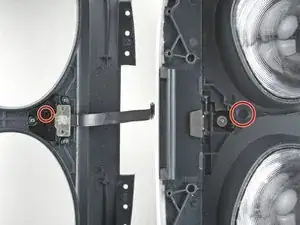
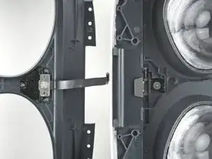
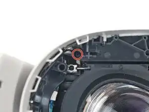
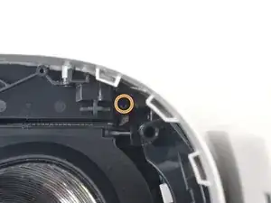
    • Use a Phillips screwdriver to remove the five 7.7 mm‑long screws securing the front cover to the headset:

    • One recessed in the top-left corner

    • One recessed in the top-right corner

    • Three along the lower edge

  20. xWRgqZ1JgWRlykWW
    xWRgqZ1JgWRlykWW
    WrousOOOoDosqXvU
    • The front cover is still held in place by clips along the bottom and side edges.

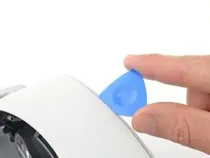
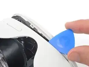
    • Insert an opening pick into the seam between the bottom edge of the front cover and the headset.

    • Pry with the opening pick to release the front cover clips.

  21. 3LnvxKG2jsGVCSgK
    3LnvxKG2jsGVCSgK
    gB5eYUFcG2kVKtTy
    Md143WrILgHS3d2T
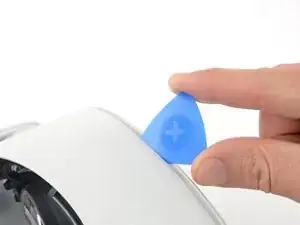
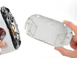
    • Slide the opening clip along the seam and pry to release all the clips securing the front cover.

  22. h1lljSnlo4ryN2NH
    • Remove the front cover.

Conclusion

To reassemble your device, follow these instructions in reverse order.

Take your e-waste to an R2 or e-Stewards certified recycler.

Repair didn’t go as planned? Try some basic troubleshooting, or ask our Answers community for help.

Arthur Shi

Member since: 03/01/18

272294 Reputation

0 comments