Introduction

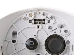
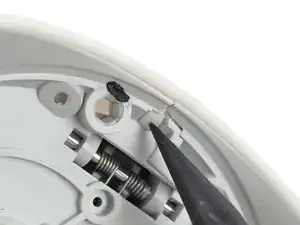
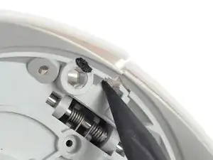
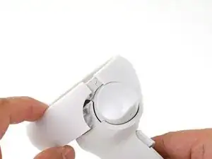
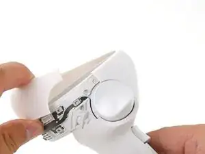
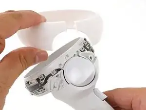
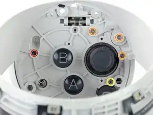
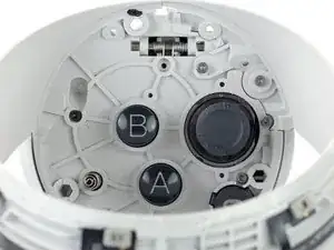
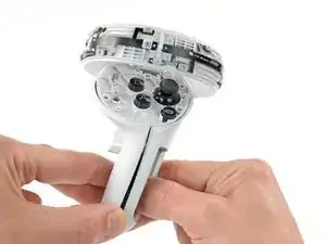
This guide shows how to remove and replace the vibration motor in your Meta Quest 2 controller.

This guide is written with the right controller. If you're repairing the left controller, you can still use this guide, as the procedure is identical.

  1. GR1vUXWJnqTqxkuD
    GR1vUXWJnqTqxkuD
    ONAX1IHTvNwdwVpt
    U4RBcddMIFYdiwYd
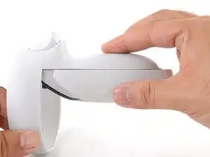
    • Use your fingers to slide the battery cover down towards the strap end of the controller.

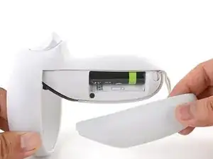
    • Remove the battery cover.

    • If you're taking the controller apart for repairs, remove the batteries in the controller.

  2. l5ONDdkdPqp1YYUJ
    l5ONDdkdPqp1YYUJ
    yY3oW3UUelHQ2vbh
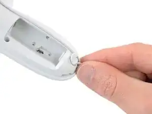
    • Use your fingers to grasp the wrist strap near the anchor peg.

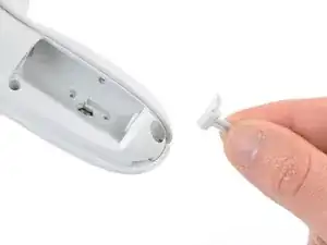
    • Lift the wrist strap anchor peg straight out of its recess.

    • Remove the wrist strap.

  3. cwCQdmhW4jcBuyva
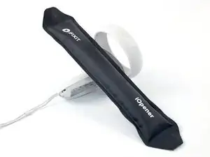
    • Heat an iOpener and apply it to the bottom edge of the controller faceplate for a minute.

    Why is this step needed? Yes there is adhesive on it, but it isn't that bad.

    DAB ARMY -

    you dont need it, prob better to have it but not required to get the cover off

    jek -

    For anyone stumbling across this like me, I can agree with the others: it is almost definitely a nice to have I'm sure, but I was able to get in just fine using an opening pick and opening tool.

    Aranohr -

  4. cBWRFaOMSrheKNcy
    cBWRFaOMSrheKNcy
    VEcbSBsWtARQjiUb
    NXB5KDisr3JacXxi
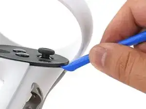
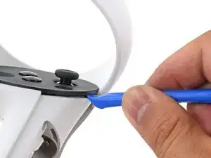
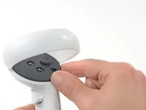
    • The controller faceplate is secured with adhesive and three friction pegs.

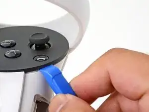
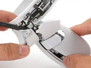
    • Press the edge of an opening tool into the seam between the controller faceplate and shell, near the Oculus button.

    • If you can’t get the opening tool into the seam, heat the area with an iOpener for a minute and try again.

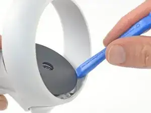
    • Slide the opening tool to the base of the ring shell to loosen the adhesive.

  5. PDjvVXVfVAHoRCrU
    PDjvVXVfVAHoRCrU
    hACIuYysbfrTTQ6Q
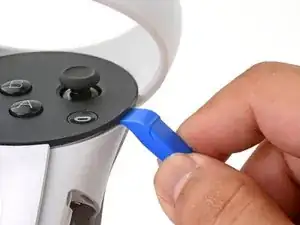
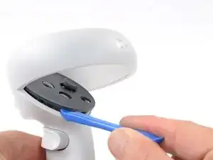
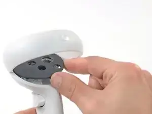
    • Use an opening tool to pry up on the seam to loosen the first friction peg.

  6. L6TLFMfcjVjmZ5RH
    L6TLFMfcjVjmZ5RH
    G6vKkvIYepj6ZSR6
    • Continue prying around the entire faceplate to separate the remaining friction pegs and adhesive.

    • If you're having trouble, apply a heated iOpener to the faceplate for a minute and try again.

  7. 5K2MXJ1XZXK4PKXf
    5K2MXJ1XZXK4PKXf
    lT1tVJWEmcJwTs6L
    UMGlJdK4d5gLMAhQ
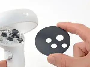
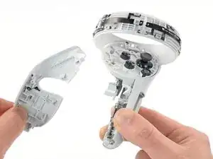
    • Remove the controller faceplate.

    • The three friction pegs should hold the faceplate securely, so you don’t need to replace the adhesive during reassembly. Be sure to firmly press the faceplate onto the controller so that all friction pegs fully engage.

  8. PDGfbm5ZliaA2nRJ
    PDGfbm5ZliaA2nRJ
    aIHSIxRvOkkCFRep
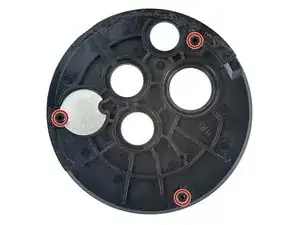
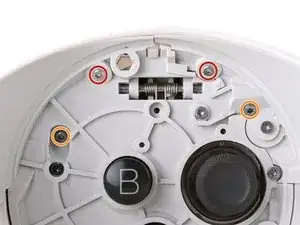
    • Use a Torx T5 driver to remove the four screws securing the controller ring shell to the controller:

    • Two 4.7 mm‑long screws

    • Two 5.9 mm‑long screws

    those top screws in red are in very tight, and at an angle that prevents using a long screwdriver. I've found the only way I could get them out is using a bit, held down by my finger at the appropriate angle, while turning it with pliers.

    Ben Klopfenstein -

    I wasn't able to remove the screws in red with a T5 bit, but switching to a T4 bit did the trick for me

    Aranohr -

  9. jOXsic4BaLufRkRi
    jOXsic4BaLufRkRi
    VdQYBkRYmwfCNeSZ
    • Press the point of a spudger firmly against the white alignment square to release the ring shell.

  10. NUA23ZwlIobRbFrV
    NUA23ZwlIobRbFrV
    41nfWd1QgMhn51Lx
    BYg2bGgQwGYqqSaK
    • Use your fingers to grab the end of the ring shell that doesn’t have the white alignment square.

    • Gently lift the ring shell up and away from the controller to unclip it from the controller.

    • Remove the controller ring shell.

  11. UJDfyoYessin2Mfo
    UJDfyoYessin2Mfo
    hgYXAh3tOgLRyNDE
    • Use a Torx T5 driver to remove the five screws:

    • One 11.5 mm‑long screw

    • Three 5.9 mm‑long screws

    • One 18.2 mm‑long screw

  12. A5wcPPi5ABScY1Mk
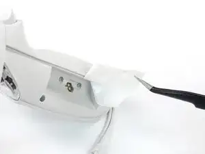
    • Use tweezers and your fingers to peel the battery information label out from the battery compartment.

    • If you want to reuse this sticker, be careful not to tear it. If it’s difficult to peel, apply a heated iOpener to it for a minute to soften the label adhesive.

  13. RCilwrZZl5CiumBo
    RCilwrZZl5CiumBo
    sCcX1FmcmEI4q6ls
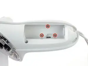
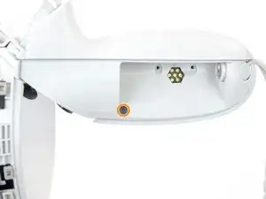
    • Use a Torx T5 driver to remove the four 5.9 mm‑long screws securing the side shell to the controller:

    • Three screws inside the battery compartment

    • One screw near the corner of the battery compartment

  14. DAXPQZwPQPH2HSDY
    DAXPQZwPQPH2HSDY
    ZytGtDyTRTxUqdkV
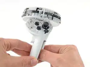
    • Pull the bottom of the side shell slightly away from the controller to loosen the shell.

    • You may hear a few clicks as the clips release. This is normal.

  15. MjR2lJcGTCVS1Efw
    MjR2lJcGTCVS1Efw
    MIOwOInaEUYr1YEa
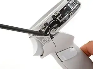
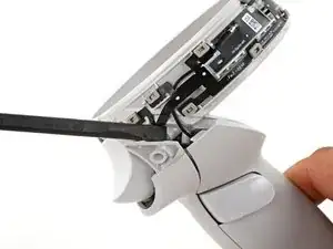
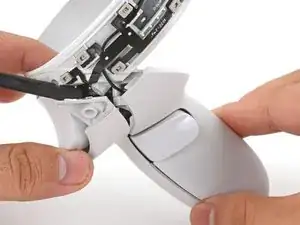
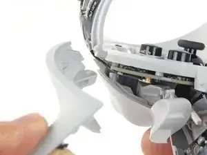
    • Part of the side shell is looped around a screw post. In this step, you’ll spread the screw post apart enough to slip the shell out.

    • Insert the flat end of a spudger into the gap between the controller ring and the front shell.

    • The front shell is the plastic frame part below the front trigger.

    • Twist the spudger to widen the gap between the front shell and the controller.

    • Position the spudger so that it can stay in place without you holding the tool.

  16. gGsilGQSy4QFJ6XD
    gGsilGQSy4QFJ6XD
    GocKeuEF3FXFgFks
    laHi6XIfgqpB2h1l
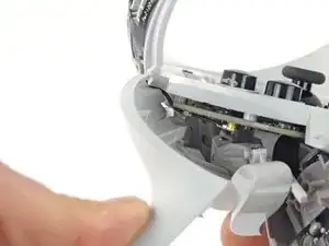
    • Guide the looped part of the side shell through the screw post gap.

    • Remove the side shell.

  17. NrhLoADuP2pdoSmY
    NrhLoADuP2pdoSmY
    CXlCWonvDjJIBN1a
    A2BKsXqTsUQG1mRY
    • During reassembly:

    • Spread the screw post wide enough to loop the side shell back around it.

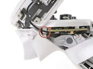
    • Be careful not to pinch the antenna cable or the tracking flex cable as you reposition the side shell.

  18. UQDM6ff5HvrJCFFr
    UQDM6ff5HvrJCFFr
    3pvinUJmKSibiEou
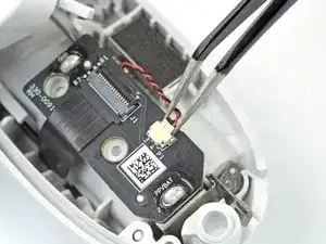
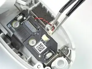
    • Use tweezers or your fingernail to pull the vibration motor connector out of its socket.

  19. IPQUpRFyF5oZnj1Q
    IPQUpRFyF5oZnj1Q
    MfLirBOju2flwPMN
    Lb4jcRVrrAJVvppW
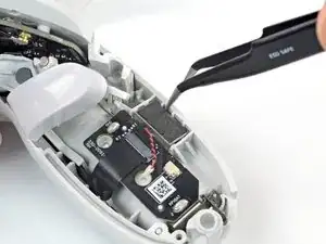
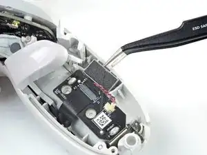
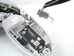
    • Insert one arm of a pair of tweezers between the vibration motor and the controller.

    • Pry to loosen the vibration motor.

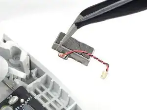
    • Remove the vibration motor.

    • The vibration motor is held in place mostly by a friction fit. If your motor feels loose when you replace it, secure it in place with some double-sided tape.

Conclusion

To reassemble your device, follow these instructions in reverse order.

Take your e-waste to an R2 or e-Stewards certified recycler.

Repair didn’t go as planned? Try some basic troubleshooting, or ask our Answers community for help.
Arthur Shi

Member since: 03/01/18

272294 Reputation

0 comments