Introduction

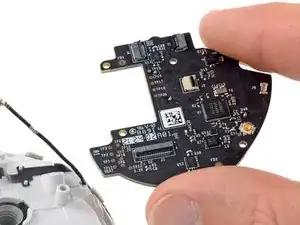
This guide shows how to remove and replace the controller board for your Meta Quest 2 controller.

This guide is written with the right controller. If you're repairing the left controller, you can still use this guide, as the procedure is identical.

  1. GR1vUXWJnqTqxkuD
    GR1vUXWJnqTqxkuD
    ONAX1IHTvNwdwVpt
    U4RBcddMIFYdiwYd
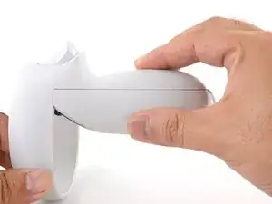
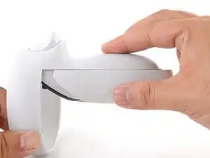
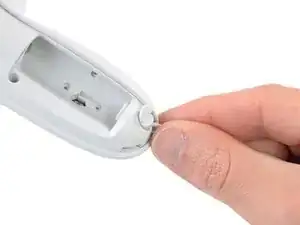
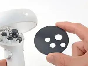
    • Use your fingers to slide the battery cover down towards the strap end of the controller.

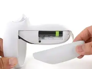
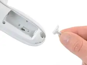
    • Remove the battery cover.

    • If you're taking the controller apart for repairs, remove the batteries in the controller.

  2. l5ONDdkdPqp1YYUJ
    l5ONDdkdPqp1YYUJ
    yY3oW3UUelHQ2vbh
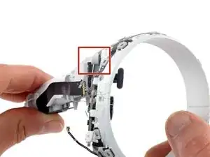
    • Use your fingers to grasp the wrist strap near the anchor peg.

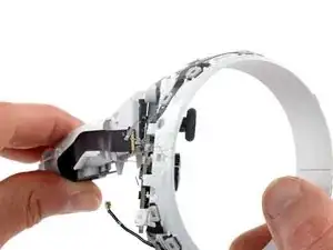
    • Lift the wrist strap anchor peg straight out of its recess.

    • Remove the wrist strap.

  3. cwCQdmhW4jcBuyva
    • Heat an iOpener and apply it to the bottom edge of the controller faceplate for a minute.

    Why is this step needed? Yes there is adhesive on it, but it isn't that bad.

    DAB ARMY -

    you dont need it, prob better to have it but not required to get the cover off

    jek -

    For anyone stumbling across this like me, I can agree with the others: it is almost definitely a nice to have I'm sure, but I was able to get in just fine using an opening pick and opening tool.

    Aranohr -

  4. cBWRFaOMSrheKNcy
    cBWRFaOMSrheKNcy
    VEcbSBsWtARQjiUb
    NXB5KDisr3JacXxi
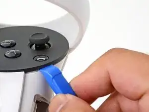
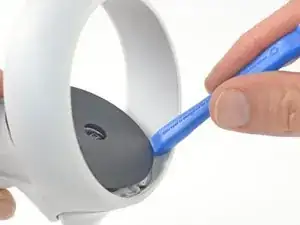
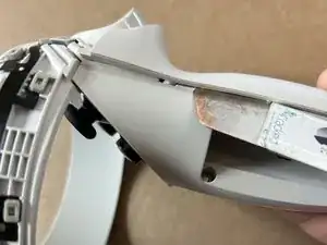
    • The controller faceplate is secured with adhesive and three friction pegs.

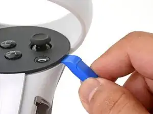
    • Press the edge of an opening tool into the seam between the controller faceplate and shell, near the Oculus button.

    • If you can’t get the opening tool into the seam, heat the area with an iOpener for a minute and try again.

    • Slide the opening tool to the base of the ring shell to loosen the adhesive.

  5. PDjvVXVfVAHoRCrU
    PDjvVXVfVAHoRCrU
    hACIuYysbfrTTQ6Q
    • Use an opening tool to pry up on the seam to loosen the first friction peg.

  6. L6TLFMfcjVjmZ5RH
    L6TLFMfcjVjmZ5RH
    G6vKkvIYepj6ZSR6
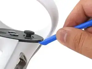
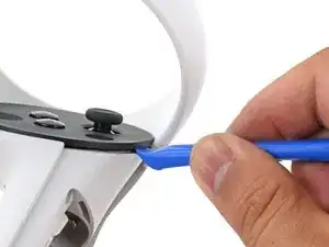
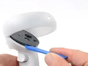
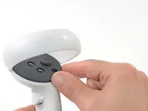
    • Continue prying around the entire faceplate to separate the remaining friction pegs and adhesive.

    • If you're having trouble, apply a heated iOpener to the faceplate for a minute and try again.

  7. 5K2MXJ1XZXK4PKXf
    5K2MXJ1XZXK4PKXf
    lT1tVJWEmcJwTs6L
    UMGlJdK4d5gLMAhQ
    • Remove the controller faceplate.

    • The three friction pegs should hold the faceplate securely, so you don’t need to replace the adhesive during reassembly. Be sure to firmly press the faceplate onto the controller so that all friction pegs fully engage.

  8. PDGfbm5ZliaA2nRJ
    PDGfbm5ZliaA2nRJ
    aIHSIxRvOkkCFRep
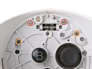
    • Use a Torx T5 driver to remove the four screws securing the controller ring shell to the controller:

    • Two 4.7 mm‑long screws

    • Two 5.9 mm‑long screws

    those top screws in red are in very tight, and at an angle that prevents using a long screwdriver. I've found the only way I could get them out is using a bit, held down by my finger at the appropriate angle, while turning it with pliers.

    Ben Klopfenstein -

    I wasn't able to remove the screws in red with a T5 bit, but switching to a T4 bit did the trick for me

    Aranohr -

  9. jOXsic4BaLufRkRi
    jOXsic4BaLufRkRi
    VdQYBkRYmwfCNeSZ
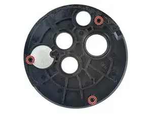
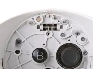
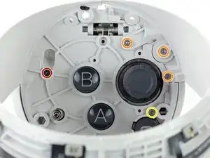
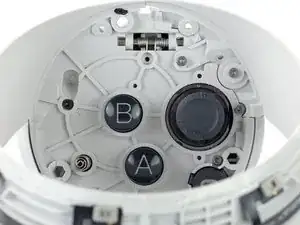
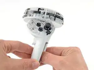
    • Press the point of a spudger firmly against the white alignment square to release the ring shell.

  10. NUA23ZwlIobRbFrV
    NUA23ZwlIobRbFrV
    41nfWd1QgMhn51Lx
    BYg2bGgQwGYqqSaK
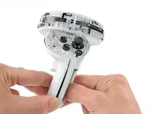
    • Use your fingers to grab the end of the ring shell that doesn’t have the white alignment square.

    • Gently lift the ring shell up and away from the controller to unclip it from the controller.

    • Remove the controller ring shell.

  11. UJDfyoYessin2Mfo
    UJDfyoYessin2Mfo
    hgYXAh3tOgLRyNDE
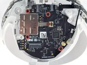
    • Use a Torx T5 driver to remove the five screws:

    • One 11.5 mm‑long screw

    • Three 5.9 mm‑long screws

    • One 18.2 mm‑long screw

  12. A5wcPPi5ABScY1Mk
    • Use tweezers and your fingers to peel the battery information label out from the battery compartment.

    • If you want to reuse this sticker, be careful not to tear it. If it’s difficult to peel, apply a heated iOpener to it for a minute to soften the label adhesive.

  13. RCilwrZZl5CiumBo
    RCilwrZZl5CiumBo
    sCcX1FmcmEI4q6ls
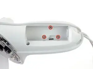
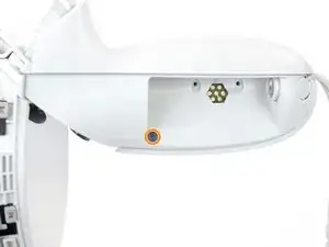
    • Use a Torx T5 driver to remove the four 5.9 mm‑long screws securing the side shell to the controller:

    • Three screws inside the battery compartment

    • One screw near the corner of the battery compartment

  14. DAXPQZwPQPH2HSDY
    DAXPQZwPQPH2HSDY
    ZytGtDyTRTxUqdkV
    • Pull the bottom of the side shell slightly away from the controller to loosen the shell.

    • You may hear a few clicks as the clips release. This is normal.

  15. MjR2lJcGTCVS1Efw
    MjR2lJcGTCVS1Efw
    MIOwOInaEUYr1YEa
    • Part of the side shell is looped around a screw post. In this step, you’ll spread the screw post apart enough to slip the shell out.

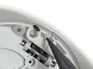
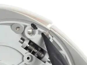
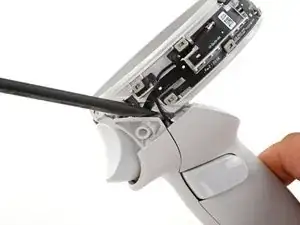
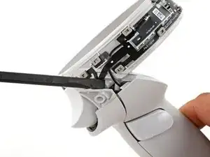
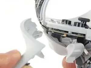
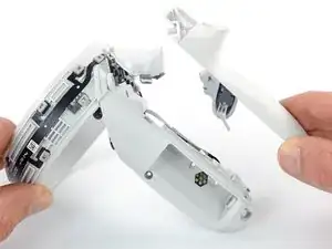
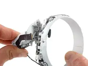
    • Insert the flat end of a spudger into the gap between the controller ring and the front shell.

    • The front shell is the plastic frame part below the front trigger.

    • Twist the spudger to widen the gap between the front shell and the controller.

    • Position the spudger so that it can stay in place without you holding the tool.

  16. gGsilGQSy4QFJ6XD
    gGsilGQSy4QFJ6XD
    GocKeuEF3FXFgFks
    laHi6XIfgqpB2h1l
    • Guide the looped part of the side shell through the screw post gap.

    • Remove the side shell.

  17. NrhLoADuP2pdoSmY
    NrhLoADuP2pdoSmY
    CXlCWonvDjJIBN1a
    A2BKsXqTsUQG1mRY
    • During reassembly:

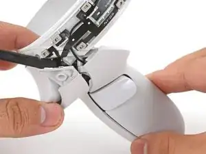
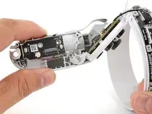
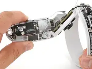
    • Spread the screw post wide enough to loop the side shell back around it.

    • Be careful not to pinch the antenna cable or the tracking flex cable as you reposition the side shell.

  18. BMTYwxgpYY2emDUY
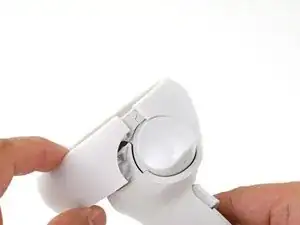
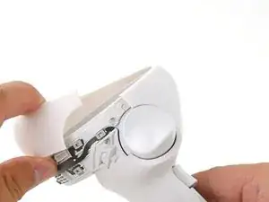
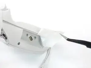
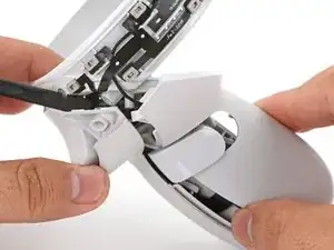
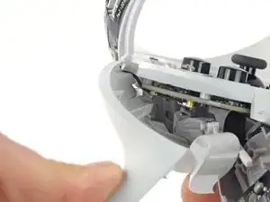
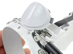
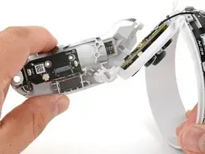
    • Use a spudger or an opening pick to gently pry the shell from the battery compartment side first.

    • Once it pops open, turn the controller over to remove the front shell.

    • If you have trouble, move to the next step.

  19. 42kPWFvSKKyOOjSl
    42kPWFvSKKyOOjSl
    lPkVGhXGBvLbgrJr
    gZ4mQDTugDwA64iY
    • If you successfully removed the front shell, skip this step.

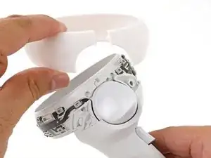
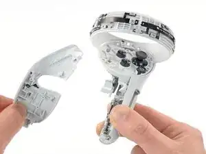
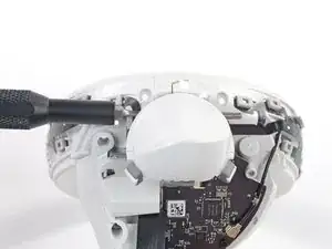
    • Grasp the front shell near the bottom of the controller.

    • Lift and pull the bottom edge of the front shell outwards slightly to clear the plastic alignment peg.

    • The alignment peg breaks easily. Make sure you lift the shell enough to clear it.

    Note: Clearing the alignment peg should not be difficult if you open the cover from the other side first as shown in my edit.

    Seby -

    Thanks Seby for your contribution! I've formatted the steps a little to include your step.

    Arthur Shi -

  20. WgxOiCiyrH55UiVa
    WgxOiCiyrH55UiVa
    Ibm5bBbZkSEdiUZM
    • Pull the front shell away from the controller and remove it.

  21. Xi1mkOCkJRHUKW1O
    Xi1mkOCkJRHUKW1O
    kTW2lUOGTiOKkqAQ
    xGWBB116bhYyKLqU
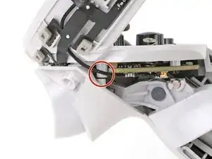
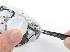
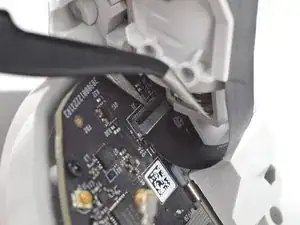
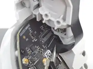
    • Use a driver bit (such as the Torx T5) or the point of a spudger to push the front trigger pin out from the side shown. Pushing from the opposite side can cause the pin to rip the sensor cable.

    • For better reach, you can also use a straightened paper clip or the point of your tweezers.

    I found this step very difficult. It required a lot of pressure to push the peg through. Make sure you push the peg from the side shown or it can tear the LED cable shown under the tip of the torx driver.

    Seby -

    This required a LOT of force on the pin to jar it loose. Just be mindful that you push in the way that nothing breaks when the pin abruptly loosens.

    eliasp02 -

  22. xSNFWAxy1mMVAfMs
    • Hold the front trigger with your finger to prevent the trigger from flying out.

    • Use tweezers or your fingers to pull the trigger pin out.

  23. cwSDLAAUbwmpmXyQ
    cwSDLAAUbwmpmXyQ
    5UuoT5cvmBnZyAQr
  24. 2LGvI1IoFW4FMfJZ
    2LGvI1IoFW4FMfJZ
    iV2YTVQdPPVJj2Xt
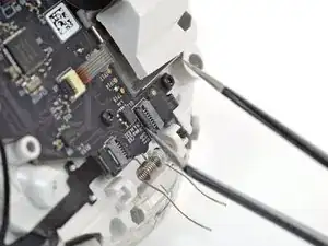
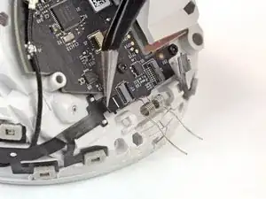
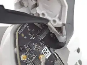
    • Use a clean fingernail or tweezers to flip up the ZIF socket's lock bar securing the outer tracking flex cable.

  25. vONKGmSPPulK3vZZ
    vONKGmSPPulK3vZZ
    3y2UelQBJiLhv6Zj
    • Use tweezers to grasp the outer tracking flex cable by its pull tab and pull it out of its ZIF socket.

  26. WJtOCxZneAyqRCrg
    WJtOCxZneAyqRCrg
    ZiCgTMa1ckIq5mPE
    HDMTWhdQQhZO6JjZ
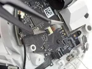
    • Use the same procedure to unlock and disconnect the inner tracking flex cable from its ZIF socket.

  27. UO2Ilp1MFByRLCfh
    UO2Ilp1MFByRLCfh
    x4P46ACtWe13bkR3
    LYAAZFBpQAnYeYLm
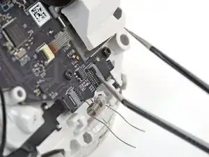
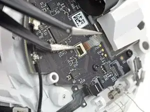
    • Use a clean fingernail or tweezers to unlock and disconnect the joystick flex cable from its ZIF socket.

  28. 64J2ThHxUZjYF3CN
    64J2ThHxUZjYF3CN
    yKFJJXVDigqZJL2j
    PuXnQk6KYRYa6KHl
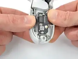
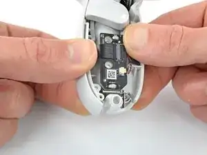
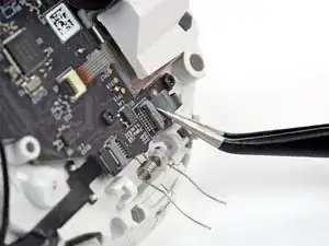
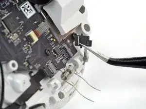
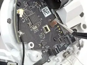
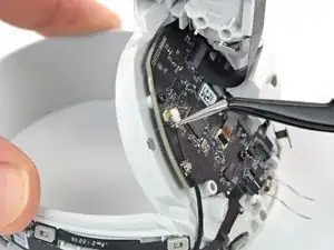
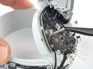
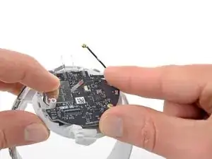
    • Insert one arm of a pair of tweezers under the metal neck of the antenna cable.

    • Pry straight up to disconnect the antenna from the controller board.

    • Gently pull the antenna to unclip it from its grounding clip.

  29. OwZEFeuIOvWAcLnH
    OwZEFeuIOvWAcLnH
    GIvqPRhCP1WCacxx
    ZgwN1EUlX3FCPoCG
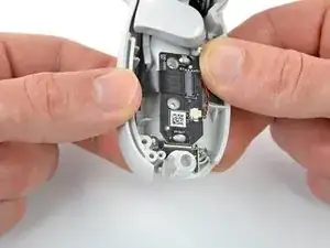
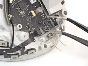
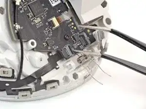
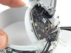
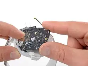
    • Use a clean fingernail or tweezers to unlock and disconnect the interconnect flex cable from its ZIF socket.

  30. VYaHZqyjsy3igmvX
    VYaHZqyjsy3igmvX
    mJt2dAU5KbpJPCjA
    r5gS5eSgnfgQvs3R
    • The battery shell is the plastic frame part that holds the batteries.

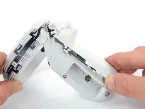
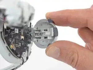
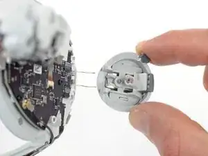
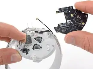
    • Use your fingers to twist the battery shell slightly so that its edge near the thumbstick clicks out of place.

  31. hJXMhCpyMwyjM65Y
    hJXMhCpyMwyjM65Y
    DOqpXOrUI2Irs4K1
    IdudbiRNutJQDM1o
    • There’s a friction assembly near the vibration motor that needs to separate in order to remove the battery shell.

    • Gently wiggle the battery shell as you pull it away from the controller.

    • Remove the battery shell.

  32. M6Cy6rGNRPlYaVpW
    • Use a Torx T5 driver to remove the four 7.5 mm‑long screws securing the controller board.

    • During reassembly, be careful not to overtighten these screws, or you may break them.

  33. Ypd5dp3ODAH1Khxm
    Ypd5dp3ODAH1Khxm
    kSKmbdgFFju5hoMJ
    PhFwn1qTRRKCLIy5
    • Use your fingers to lift the controller board out of the shell and remove it.

    If the joystick spring came out during disassembly - make sure to put it back under the board before screwing it in!

    Murray Groves -

Conclusion

To reassemble your device, follow these instructions in reverse order.

Take your e-waste to an R2 or e-Stewards certified recycler.

Repair didn’t go as planned? Try some basic troubleshooting, or ask our Answers community for help.

Arthur Shi

Member since: 03/01/18

272294 Reputation

2 comments

Where can I purchase a controller board for my Meta Quest 2 right controller?

Scott Hepler -

How can I reattach the ZIF socket to the circuit board?

Toni Jones -