Introduction
Having issues with your 6.5”/7”/12.3” Medallion Smart Touch Display? You’ve come to the right place.
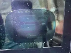
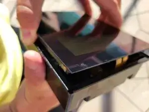
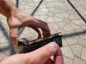
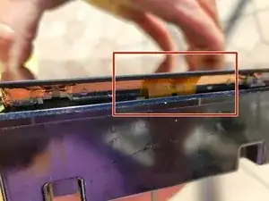
Many boats are experiencing delamination, causing a bubbling or peeling appearance.
This leads to lost touch response and other issues.
We have engineered replacement display panels that utilize a superior bonding method for a permanent fix, rather than the original LOCA liquid that is prone to delamination over time.
-
-
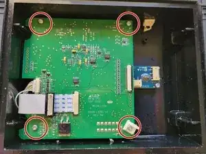
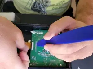
With screws removed, remove the main board from the housing.
-
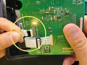
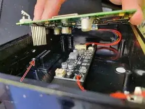
Gently push the pins from the back to help guide the board out
-
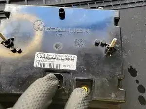
For Tige owners- you can push on the yellow plug also to guide the board out through the rubber grommet seal.
-
-
-
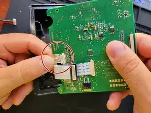
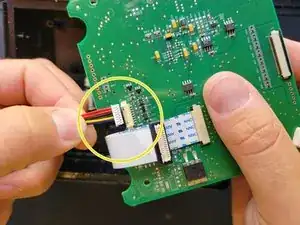
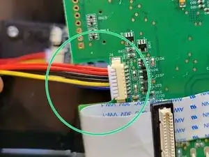
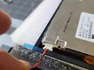
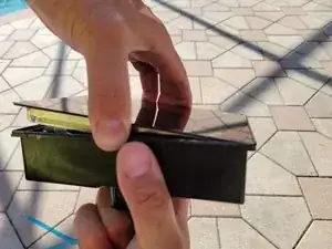
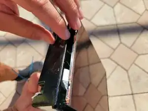
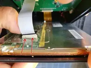
Grip the white wire in one hand and the board in the other.
-
Pull the white cable harness out of the board.
-
-
-
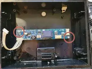
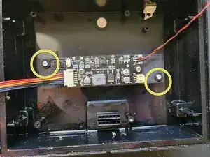
Remove these two T10 screws.
-
Do not throw away the screws, they will be reused.
-
You can scrap the old backlight driver, it is obosolete.
-
-
-
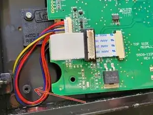
Place the spacer assembly found in your LED retrofit kit on the housing posts as shown. Make sure the rainbow cable is on the left side when the harness is at the bottom like in the photo.
-
Use the T10 screws from the previous step, along with the provided nylon washers to mount the spacer assembly.
-
Do not overtighten the screws, hand tight is fine.
-
-
-
Press the rainbow cable to the main board as shown.
-
Make sure it is fully seated straight in the connector.
-
-
-
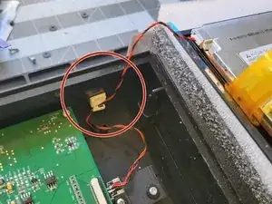
Route the rainbow cable as shown around the bottom post to take up the slack.
-
Guide the pins through the proper holes- do not bend or force the pins.
-
Avoid pinching the wires in the housing.
-
For Tige owners- you can use a bit of isopropyl alcohol to lubricate the rubber grommet seal to help the yellow plug slide through.
-
-
-
Insert plug to LCD as shown. Be gentle, do not force it. It can only go in one way.
-
Secure excess cable to the existing tie point if available. If there is no tie point, just stuff the wire under the main board.
-
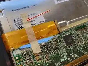
Remove protective masking tape from digitizer cable
-
-
-
Place the LCD panel on an elevated surface as shown.
-
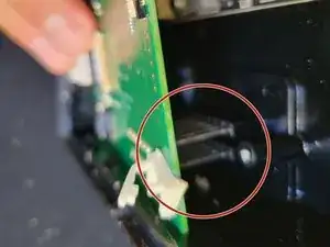
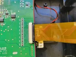
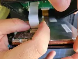
With digitizer locking clip unlocked as shown, carefully insert the ribbon cable. Avoid stressing the cable, it is delicate and you don't want to tear it.
-
Hold the digitizer cable all the way in and straight, and use your blue tool to click the locking tab closed evenly.
-
The cable must be in and straight. Use the edge of the board as a reference point.
-
-
-
In the coming steps, you want to support the housing with your left hand and the LCD panel with your right hand. Do not allow the parts to hang from the cables.
-
Align the right edge with the right lip of the housing as shown. Do not pinch the orange ribbon cable. Tuck it in while aligning the edge.
-
With the right edge of the glass on the lip, tilt the left side of the LCD towards the left side of the housing.
-
-
-
Reach in and fully insert the white cable to the plug. It will be flush when its fully inserted.
-
The two little box cut outs will show the plug when its fully seated.
-
-
-
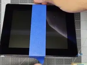
Apply a easy-release yellow or blue painters tape, or even scotch tape, to temporarily hold your LCD panel in while you plug it in your boat and test the functions.
-
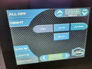
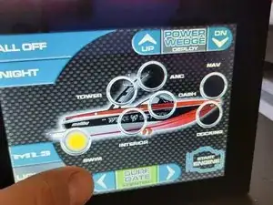
Test all functions and features.
-
The purpose of the tape is to keep the LCD panel from falling out during testing.
-
If the touch isn't working, or the LCD panel is not lighting up, open the unit back up and verify all the connections are correct.
-
-
-
Lift the LCD panel up and remove the right side protective tape backing film. Tuck the orange ribbon cable and prevent it from getting pinched in the tape.
-
Align the right edge of the glass to the lip, with the orange cable NOT pinched.
-
Proceed with removing the other protective tape backing films.
-
Place the LCD in the lip while avoiding pinching cables.
-


To reassemble your device, follow these instructions in reverse order.