Introduction

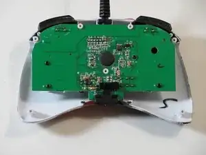
Use this as a guide to repair the USB cable when its internal connection to the controller is damaged.

  1. pm416YSWvG5ucNwk
    • Use tweezers to completely remove the sticker from the rear of controller.

  2. 3uXvLlgQHkmtRRUM
    • Find the seven 8.3 mm Phillips screws on the rear of the controller and remove them.

  3. FumE6DnlEejBvJim
    FumE6DnlEejBvJim
    EOnKxbsxMUVWcPcp
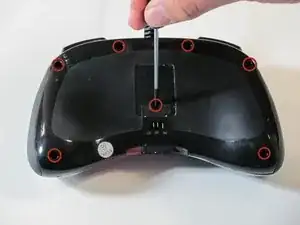
    • Use a plastic opening tool to separate the rear and front casing by inserting it in-between the two cases.

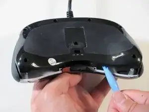
    • Use the plastic opening tool to pry the two cases apart.

  4. VVEjO1MLOoycT6Qt
    VVEjO1MLOoycT6Qt
    IJqQCC1YUNNyCDK3
    • Remove the two rubber side grips.

  5. 6mf2FoIsZRtoAyTA
    6mf2FoIsZRtoAyTA
    unvODXCdUGvmTYGU
    • Locate RS-DP-LS switch.

    • Pull upwards on the switch to remove it.

  6. viIJjwUHe2BtVuuD
    • Locate the four 8.3 mm Phillips screws on the circuit board and remove them.

  7. hiophYM5WgcCxTmQ
    hiophYM5WgcCxTmQ
    s33OpVCF5QyrPnlp
    fJSaAKgMbFlQCEAW
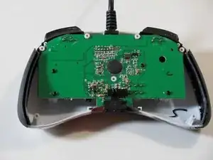
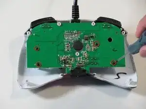
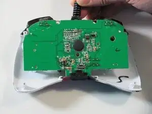
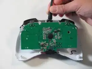
    • Hold the controller cable at the area just before it meets the controller and slowly lift upwards to slide it out of its plastic slot and remove the circuit board.

    • Be careful with the wires connected to the circuit board itself as they are thin and delicate.

    • When reassembling the controller, make sure that the bottom plastic piece is fully inserted into its slot before replacing the circuit board.

  8. rGXqTjiHbWHRkW4T
    rGXqTjiHbWHRkW4T
    QDbxxC2YvhQIiEEQ
    SvTbnXMGEqP11tRU
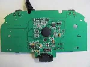
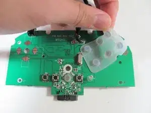
    • Orient the motherboard so that the side with the rubber buttons is facing up.

    • Remove the rubber buttons by pulling up on the on the rubber pad on the points where the rubber cylinders that poke through the motherboard are so that each cylinder slides out nicely.

    • Removing the rubber buttons is optional but recommended to do before soldering.

  9. mIfyqQrYnMNhsE1Z
    • Locate the broken or disconnected wire by gently pulling up on the five wires connected to the motherboard

  10. IJLf4SEWjVR1yrMg
    • Push or pull the broken or disconnected wire through its respective hole on the front side of the motherboard so that the metal part of the wire is sticking out the back side of the motherboard.

    • Use the soldering kit to solder the wire onto the back side of the motherboard.

    • You may need to desolder the old solder in the hole before pulling the wire through and soldering it to the motherboard.

    • If the rubber sleeve of the wire prevents the metal part of the wire from going through the hole then use tweezers to pull the rubber sleeve back to expose more of the metal part.

Conclusion

To reassemble your device, follow the instructions starting from step eight in reverse order.

For specific instructions on soldering, check out the iFixit soldering guide.

Eric

Member since: 26/09/12

117 Reputation

0 comments