Introduction

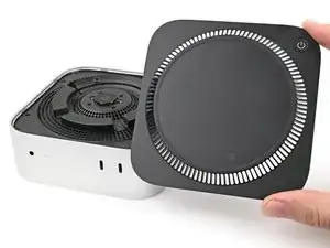
Use this guide to replace the front USB-C ports in your Mac mini (2024).

This guide was written with a baseline M4 Mac mini. Although the internals for the M4 Pro version are slightly different, the disassembly procedure is the same.

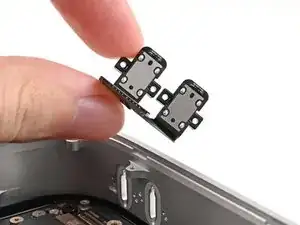
The two front USB-C ports are combined into one part, so replacing one port means replacing both.

  1. 2AOCDRumFYCwLHDo
    2AOCDRumFYCwLHDo
    oPNVEBC3oT2PmroR
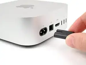
    • Fully shut down your Mac mini and unplug all cables from it.

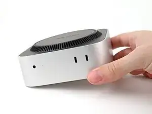
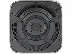
    • Flip over your Mac mini and place it on a clean, flat surface to avoid scratching the chassis.

  2. GAqAsFlbHCjSAv5v
    GAqAsFlbHCjSAv5v
    CRy6ImTIPFvNigGN
    XCXS3xLkfcRUsRMF
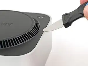
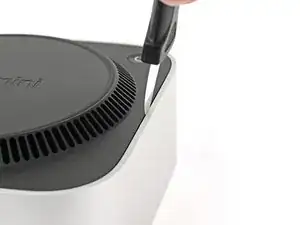
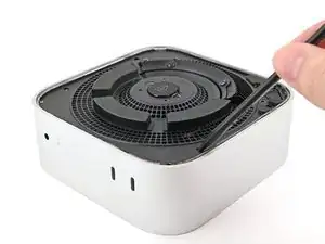
    • Insert a Jimmy into the gap between the bottom cover and the chassis.

    • Pry up the bottom cover to create a gap.

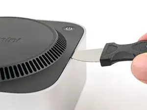
    • Keep the Jimmy inserted under the bottom cover.

  3. oIn1d3q2dsgFbK4P
    oIn1d3q2dsgFbK4P
    HqjtQvKCBFw2J4PR
    GqIosShyLUtCj1nG
    • Insert an opening pick into the gap created by the Jimmy.

    • Remove the Jimmy.

  4. a1s5oNAhMIPhEdZF
    a1s5oNAhMIPhEdZF
    OjcPUDbawZTxsBPI
    3iNDpG2UcdWeM3Wp
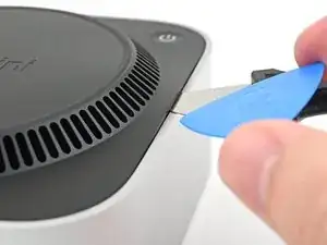
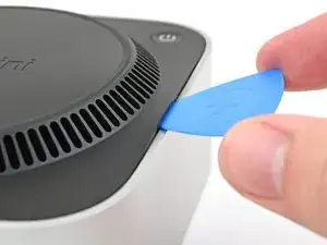
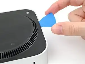
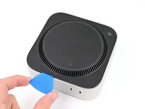
    • Slide the opening pick along the bottom cover until you feel it snag on a clip.

    • There are four clips total—one at each corner of the bottom cover.

    • Twist the pick to lift the clip out of its slot.

  5. cOUhCJYM1rcSehRM
    cOUhCJYM1rcSehRM
    UdUOJBvlO1sVS62f
    RdtnPQiopAujHrbS
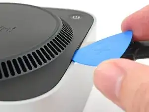
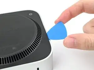
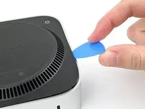
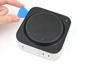
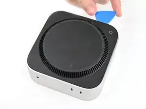
    • Continue sliding and prying with the pick along the perimeter of the bottom cover to release the remaining clips.

    • Don't insert the pick more than an inch near the power button, as you risk damaging the cable.

    • During reassembly, press along the perimeter of the bottom until you hear and feel all four clips click back into place.

  6. vZyG2Wn2rE61iQM2
    vZyG2Wn2rE61iQM2
    hBV4exmuJXURVt5B
    • Don't remove the bottom cover yet, as it's still connected to the Mac mini with a cable.

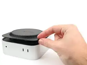
    • Lift the edge of the bottom cover opposite the power button and flip it over to expose the power button cable.

  7. 5CfDOyQWJK5PKgRB
    5CfDOyQWJK5PKgRB
    OMZdwUb1RCYfr43I
    P2UWtvWdIv1Y1FXJ
    • Grip the power button cable close to the head and pull it away from its socket to disconnect it.

  8. kIgBGpKoOr1RhIMk
    • Remove the bottom cover.

  9. NLf1LQKf2EByNkT1
    NLf1LQKf2EByNkT1
    DcQJCakPCYwAQHYv
    • Throughout this repair, keep track of each screw and make sure it goes back exactly where it came from.

    • While the Mac mini uses Torx Plus screws, standard Torx bits work. Make sure to apply constant, downward force to prevent stripping.

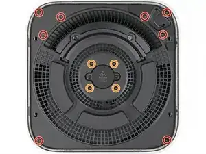
    • Use a T5 Torx screwdriver to remove the twelve screws securing the inner plate:

    • Eight 3.4 mm‑long screws

    • Four 2.4 mm‑long screws

  10. DaRruNxTSRSMoPrJ
    DaRruNxTSRSMoPrJ
    xIvW2Ga1HDNfAqAh
    tkhfWhrlXPqIFKhB
    • Insert the point of a spudger into one of the clips' slots on the inner plate.

    • Pry up the inner plate enough so you can grip the edge along the same side as the headphone jack.

  11. dB3mwJYHa2qhHlEE
    dB3mwJYHa2qhHlEE
    gDjuFpfSeZEIJMDH
    • Pull the inner plate away from the chassis to slide it out from under the lip on the heat sink.

    • During reassembly, slide the inner plate back under the heat sink and press along its edges to secure it in the chassis.

  12. hJ6Eco3cIauvclxp
    hJ6Eco3cIauvclxp
    Ykn6L3XvOPaIbw41
    1HKVWUnFLwR5OJSP
    • Don't remove the inner plate yet, as it's still connected to the Mac mini by a cable.

    • Lift the inner plate and flip it over to expose the wireless module cable.

  13. J4yIxef1cTpYUjpK
    J4yIxef1cTpYUjpK
    Kb5sW2OrWZeqkg2a
    k1PbMLAJLMtyy1hw
    • Use one hand to secure the wireless module during this step.

    • Use a Torx Plus 5IP screwdriver to remove the four 2.5 mm‑long screws securing the wireless module cover.

  14. fwajrKpV6ZjfmcHW
    fwajrKpV6ZjfmcHW
    DcP26NvgyCyWTCpF
    • Remove the wireless module cover.

    • During reassembly, look the bottom of the cover to find the foam rectangle. Align the foam rectangle over the wireless module press connector to find the proper orientation for the cover.

  15. sATvVqPyyQAv3u4Y
    sATvVqPyyQAv3u4Y
    IyrMKIBvCdLSKeup
    • Use one hand to secure the wireless module during this step.

    • Insert the point of a spudger under one of the short edges of the wireless module press connector.

    • Don't insert your spudger anywhere else, as you risk dislodging surface-mounted components.

    • Pry up to disconnect the wireless module.

  16. sTQHsvG16sVhsxGp
    • Remove the inner plate.

  17. qdYFTlKulBTNMRRm
    qdYFTlKulBTNMRRm
    ckNuJ1yit6VQsZ4X
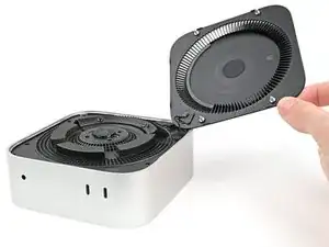
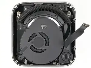
    • If you're following this guide to clean your fan, this is a good time to do so.

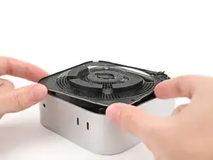
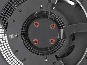
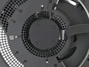
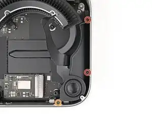
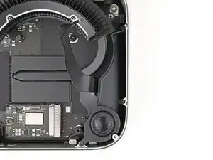
    • Remove the four screws securing the fan:

    • Two 2.4 mm‑long Torx Plus 3IP screws

    • Two 7.9 mm‑long Torx Plus 5IP screws

  18. jTTmxtU5sE32f3HH
    jTTmxtU5sE32f3HH
    gLodSHEXW6bfCfbH
    JJvGIlBYDIIZncL6
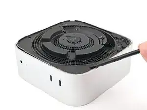
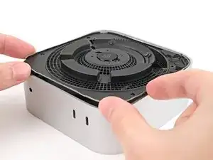
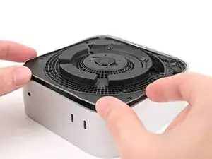
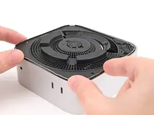
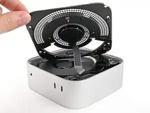
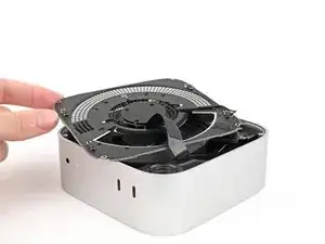
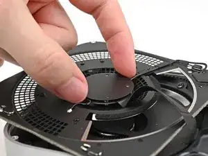
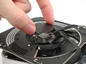
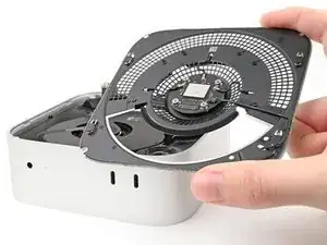
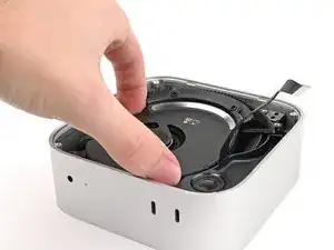
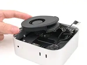
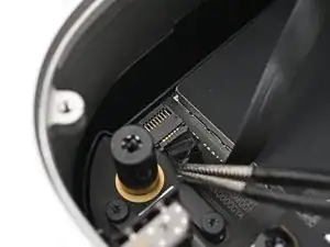
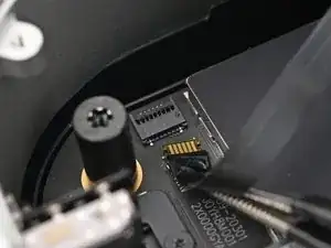
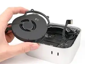
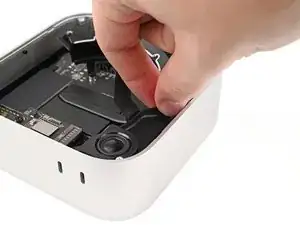
    • Lift the fan out of its recess in the chassis and flip it over to expose its wire and connector.

    • Let the fan rest on the chassis and heat sink.

  19. YJjld2EvOeNDRNU2
    YJjld2EvOeNDRNU2
    QmZ1PwqNePOSWDVI
    Aep5IXHPLy4eN4r6
    • Use tweezers to peel back the tape covering the fan ZIF connector.

  20. ig6kBeoAiQyIQDaV
    ig6kBeoAiQyIQDaV
    oV2TCDAlS35dAJPW
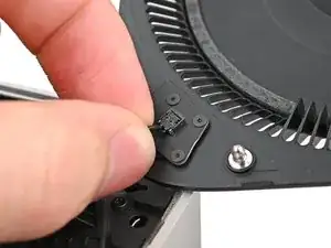
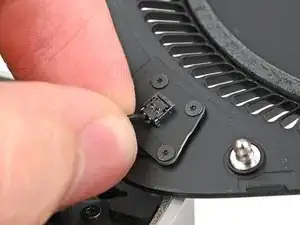
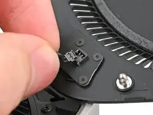
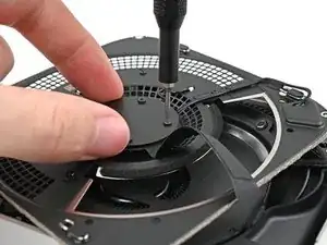
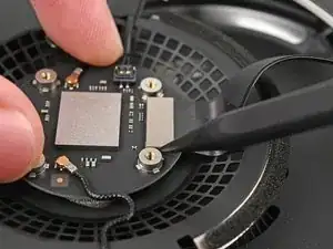
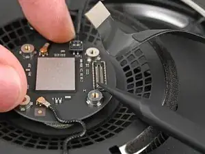
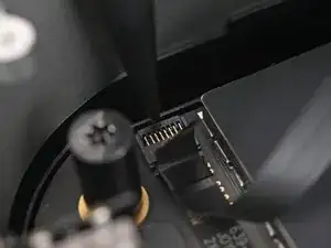
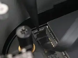
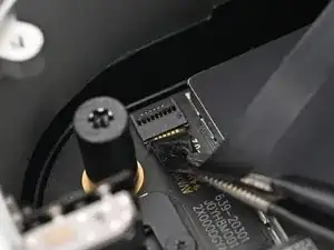
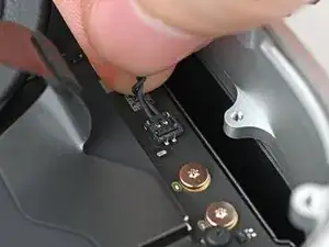
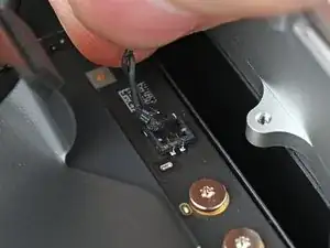
    • Use the point of a spudger, or your fingernail, to flip up the locking tab on the fan ZIF connector.

  21. 31E6CDAiyiVoWup1
    31E6CDAiyiVoWup1
    l2XNxPRVuR2ndOpl
    • Use tweezers, or your fingers, to slide the ZIF connector straight out of its socket.

  22. r24gIAKSEArHcDNb
    • Remove the fan.

  23. Fk3fqNZ5P4bXU4SW
    Fk3fqNZ5P4bXU4SW
    6sxSYPRPD1ZOUpRB
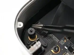
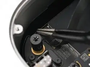
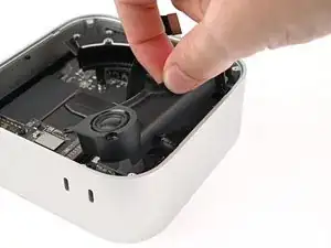
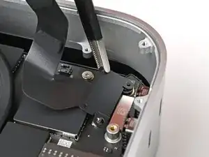
    • Use a Torx Plus 5IP screwdriver to remove the three screws securing the speaker:

    • Two 4.1 mm‑long screws

    • One 3.7 mm‑long screw

  24. S4WoK4IHXoHFeBJT
    S4WoK4IHXoHFeBJT
    PaqyF41lFOMAQTtq
    OIOks4MHKfNIEAJ3
  25. IDjiL6tBTfEXENJv
    IDjiL6tBTfEXENJv
    2qoHLPnLRS4sPtJq
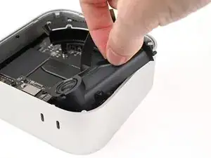
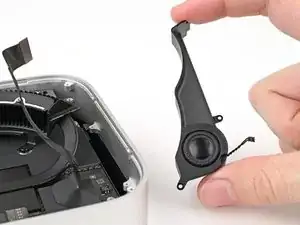
    • Pull the speaker over the edge of the chassis to expose its cable and its connector.

    • Rest the speaker on the edge of the chassis.

  26. Hh42HFMQESOIOSvo
    Hh42HFMQESOIOSvo
    hOuiYFIqUTW1OhwC
    QVv6udFlSyGXjOVB
    • Grip the speaker cable close to the head and pull it away from its socket to disconnect it.

  27. 5kFeWlgnQcxdQyuV
    • Remove the speaker.

  28. qc5jtfbXMWqZVuey
    qc5jtfbXMWqZVuey
    OjuAZTFfESCWBMpD
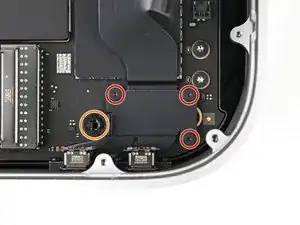
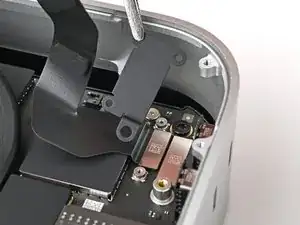
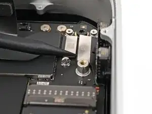
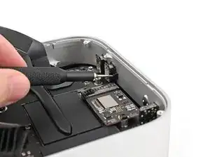
    • Remove the four screws securing the USB-C port cover:

    • Three 2.2 mm‑long Torx Plus 3IP screws

    • One 9.2 mm‑long Torx Plus 8IP screw

  29. wQodHSUPnFBcj3HB
    wQodHSUPnFBcj3HB
    CKEfupYIY1hmtCI5
    • Use tweezers, or your fingers, to remove the front USB-C port cover.

  30. fGLxKkNZRSdhNNPa
    fGLxKkNZRSdhNNPa
    2ftsRStC2hJwTMOg
    • Use the point of a spudger to pry up and disconnect the front USB-C ports press connector.

  31. J5oiKYMKZhDUCirT
    J5oiKYMKZhDUCirT
    p3FZ3SnUJOGaUhR2
    YK5YTOJKEG5PBUVh
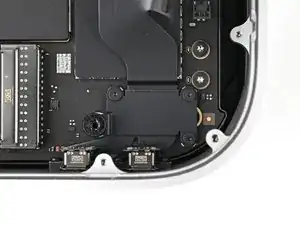
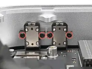
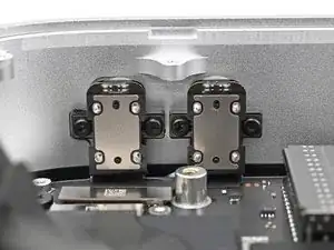
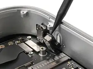
    • Use a Torx Plus 3IP screwdriver to remove the four 4.7 mm‑long screws securing the two front USB-C ports.

    • If you aren't using a flexible adapter, make sure your screwdriver is as parallel with the screw as possible. Apply constant force against the screw to avoid stripping.

  32. 2M3HxD5iaMVTtZua
    2M3HxD5iaMVTtZua
    EQxVyfKLEAgGqZoZ
    Y1llmRuOoRhtPoY5
    • Use the point of a spudger to pry the front USB-C ports from their recesses in the chassis.

    • During reassembly, gently press the USB-C ports into their recesses until they click into place.

  33. hAKTMoh3Liu2QvpU
    hAKTMoh3Liu2QvpU
    3RCOBdZULrGuy5DC
    • Pull the front USB-C ports out of the chassis and remove it.

Conclusion

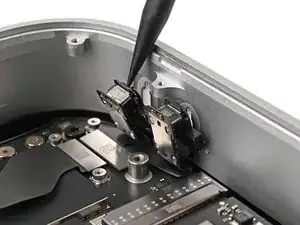
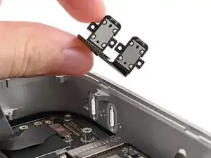
To reassemble your device, follow these instructions in reverse order.

Take your e-waste to an R2 or e-Stewards certified recycler.

Repair didn’t go as planned? Try some basic troubleshooting, or ask our Mac mini (2024) Answers Community for help.

Alex Diaz-Kokaisl

Member since: 16/01/22

151895 Reputation

0 comments