Introduction

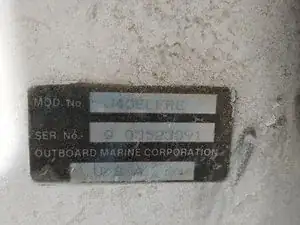
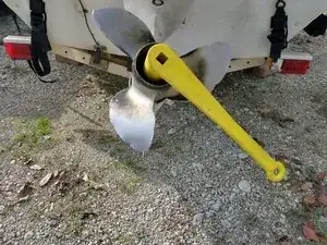
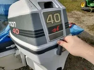
This is a three part Lower Unit Service on a Johnson 40 boat motor. Model Number: J40ELERE

  1. F4GI1BJ6wbWSvydp
    F4GI1BJ6wbWSvydp
    NaLN3CUwOaVvd3AG
    nSgRWIaGTUKvJHpB
    • Remove the cotter pin that is stuck through the propeller shaft using a pair of pliers.

    • You can reinstall the old cotter pin, but it will be easier to install a new one.

  2. ZHMUNbjA3rjMX4cO
    ZHMUNbjA3rjMX4cO
    SOtTmX4hUffkTgNS
    kAHlAVNjQFkgqSLO
    • Using the special wrench, loosen and remove the castle nut.

    • Behind the castle nut will be a washer, set the washer on top of the castle nut to help remember the order in which everything comes off.

    • When tightening the castle nut, make sure not to block the hole for the cotter pin

  3. JYVpMmiSiQgmIWSv
    • Remove the propeller.

    • There is another washer behind the propeller that may come off with the propeller, check for this before installing new propeller

  4. EiahZFGDgdiSovQp
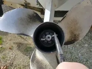
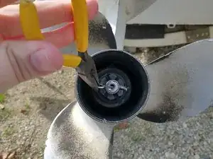
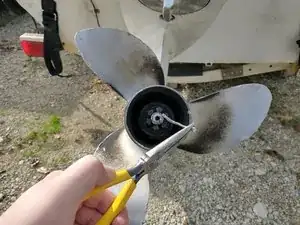
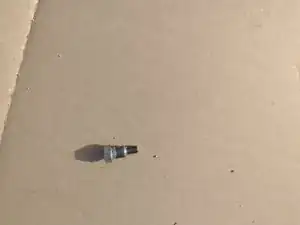
    • If the washer behind the propeller did not come off with the propeller, remove it and set it aside with the propeller, other washer, and castle nut.

  5. M4wEGwCULFfsK2bF
    M4wEGwCULFfsK2bF
    qYrBoqBfWoiiMxVs
    • Remove the two screws on either side holding the anode in place using a 5/16 nut driver.

  6. OWgJeBUORCvkTnPc
    • Pull the anode out

    • Reverse the previous steps to reinstall

  7. pxGHShUt4HrVyQy2
    pxGHShUt4HrVyQy2
    YhB5JdPhmTZsCUg6
    • Remove upper cowl by turning the black levers on the front and rear of the cowl

  8. eOLvFBUYIZBAuxc1
    eOLvFBUYIZBAuxc1
    fRT2dDBlxeeJOjTJ
    qSOjXphuwVhcE6Rv
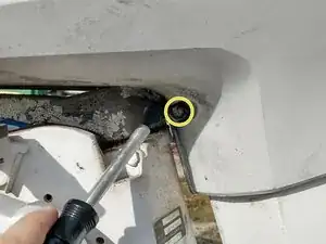
    • Remove the lower cowl by removing the one 3/8 in bolt from the front

    • the two 3/8 in bolts from the rear of the lower cowl

    • One bolt is under the rear latch

    • the 3/8 in bolt under the bottom of the lower cowl. This is most easily done using a universal-joint socket.

  9. 2Fk1HPgwbWvFLoGs
    • Trim the engine all the way up and pull the two halves away from the engine and downward, removing the rubber holders for the battery connection and control cables

  10. xQhfSxntmaGGKX66
    xQhfSxntmaGGKX66
    r3IeTdhNJbFMxDsM
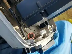
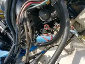
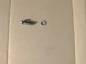
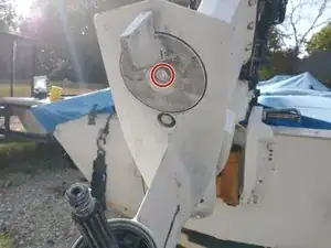
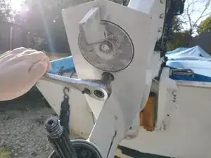
    • Remove the 3/8 in screw connecting the vertical shift linkage going into the lower unit to the horizontal shift linkage in the upper unit. This Is located directly below the block on the port side of the engine.

    • this is a special tapered bolt

  11. Eypxi6ByGU4oE5K5
    Eypxi6ByGU4oE5K5
    r1nbJvgqYtk3vJKZ
    5iNwVOarTnwRcsAg
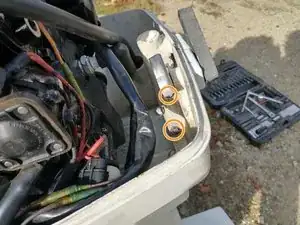
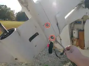
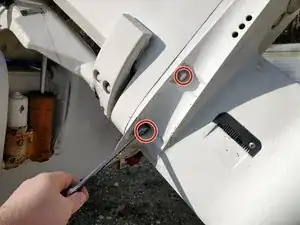
    • Remove the four 9/16 in bolts connecting the lower unit to the upper unit. This will need to be done with a regular wrench.

    • These bolts have washers

  12. UwBgUYelHKGBPQao
    UwBgUYelHKGBPQao
    UxikfYHX2KE3vF1D
    pAb5IFplPsOVmnYU
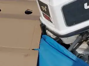
    • Remove the one 5/8 in bolt holding the lower unit to the upper unit. This is located directly above the propeller. As you do this the lower unit will begin to pull away from the upper unit.

    • Make sure to align the shift linkage with the bracket that holds it before fully tightening the bolt

    • the lower unit may begin to slip out after this bolt is removed.

  13. LS6TqfYLN5IhT6ID
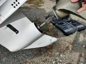
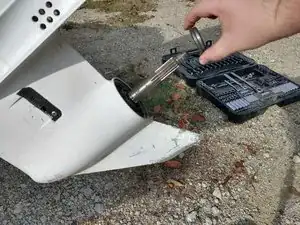
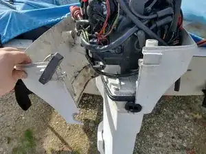
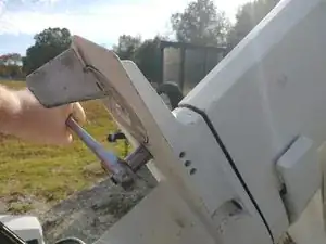
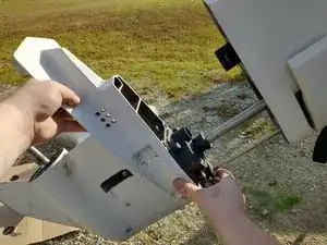
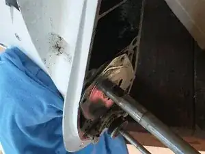
    • Remove the lower unit from the upper unit by gently pulling the lower unit straight away from upper unit, taking care not to bend the shaft or shift linkage.

    • If the lower unit seems stuck, gently wiggle it until it comes out freely

    • 8. Place the lower unit on a table or put it up in a vice if one is available. This needs to be a clutter free workspace to ensure that the small parts in the water pump can be found if dropped

    • If you do put it in a vice, do not over tighten and use soft jaws if possible or a rag you can’t use soft jaws to protect the lower unit from being scratched or dented.

  14. vdriiH6jHTtIcOM5
    vdriiH6jHTtIcOM5
    DZZcP3EhpTB6Qqdu
    qRm2UFUKF3BvTDmE
    • Remove the four 7/16 in bolts holding the water pump to the lower unit

  15. Vd44SLkVnuZLfsrC
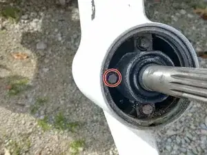
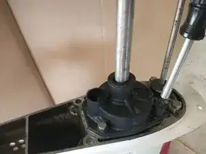
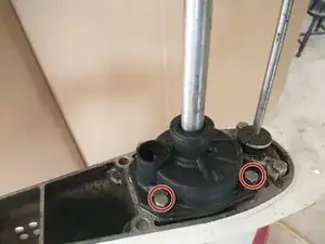
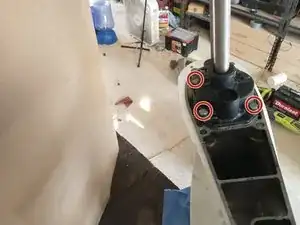
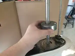
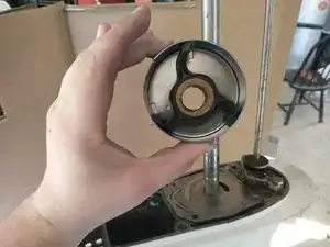
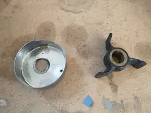
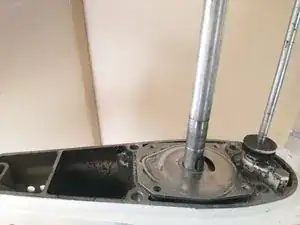
    • Remove the outer water pump housing by sliding it up the shaft. This should expose the inner housing.

  16. MEPOMy16SSXMFg2l
    MEPOMy16SSXMFg2l
    fPJV2Yk5MnFudCWQ
    BVRsnOWlPGUQ4TW1
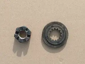
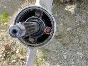
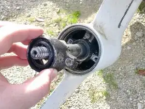
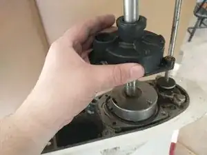
    • Remove the inner housing. The impeller should be stuck tightly inside the inner housing and will come off with it.

    • The impeller has a key that holds it to the shaft that will fall out, be careful not to lose it.

  17. DmhbjKsVKNw5vnXj
    DmhbjKsVKNw5vnXj
    crIXdv5wMGnhct1L
    • Remove the old impeller from the housing and install the new one.

    • Make sure the side of the impeller with the grove for the key will be facing downward when installed.

    When installing the new impeller be sure the fins are bent in the right direction so it turns with the shaft properly. If not it can damage the new impeller at start up.

    Doug -

  18. CJjnM6AaTV4ammTF
    CJjnM6AaTV4ammTF
    QuZPHSTiEMnFtHGb
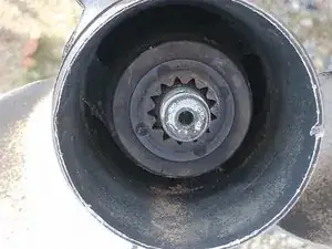
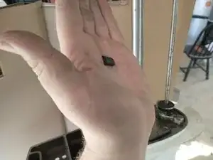
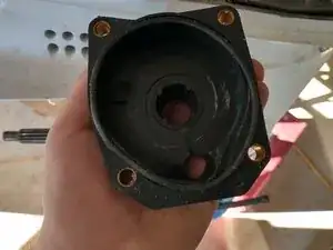
    • To replace the impeller and inner housing, first put the key into the notch on the shaft and slide the impeller and inner housing down the shaft lining up the key with the notch on the impeller.

    • It may be beneficial to turn the lower unit on it’s side so that gravity will hold the key in place.

  19. 3aGgvYMfPCh2NViL
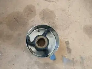
    • Slide the housing down the shaft and make sure the seal for the outer housing is sitting in the grove on the underside of the outer housing.

    • If the outer housing does not want to go over the inner housing, slowly rotate the shaft while applying gentle downward pressure to the upper housing until it slides into place.

    • To finish installation, follow the removal steps in reverse starting at step 9

Conclusion

To reassemble your device, follow these instructions in reverse order.

Elijah Durkee

Member since: 12/11/21

361 Reputation

0 comments