Introduction

  1. qgF1BFXUkFhPLkHH
    qgF1BFXUkFhPLkHH
    gxI3WZBS4FwEeCpa
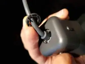
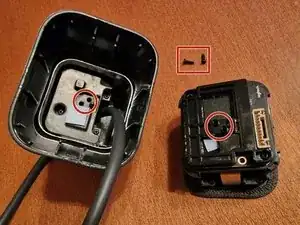
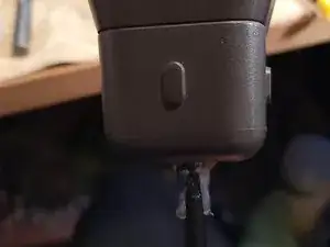
    • Be mindful of keeping the lens glass away from abrasives when disassembling. Turn the camera over and use your plastic spudger (pry tool) to pop out the plastic ring obscuring two small screws.

    • NOTE: many fixers may find that replacing only the distal USB-C plug is needed. In that case, you needn't open the camera or replace the cable -- just skip to the wiring explanation in step 4, and get a new USB 3.x type-A or type-C male plug.

  2. KiCpgV3cTJIAdFck
    KiCpgV3cTJIAdFck
    6BPynHPYLlQHvZMc
    iiL31NLVZWNylavL
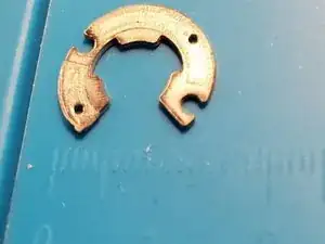
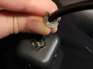
    • Once the screws are removed, the retention ring easily separates from the cable moulding with firm prying or pulling pressure. It's a C-clip with some light adhesive facing outward.

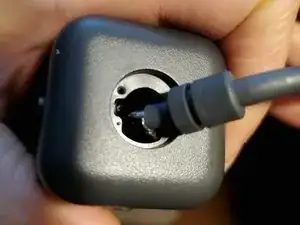
    • After the retention clip is out, peering into the housing will reveal two identical 000 screws that hold the camera subframe to the outer shell. Remove these (they'll easily shake out if not pulled out with your screwdriver's tip).

  3. qmTaRrPSlpIlCDCR
    qmTaRrPSlpIlCDCR
    TEGruLxp3Nuegi44
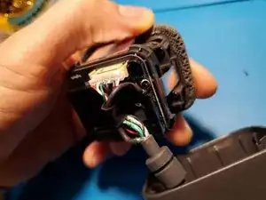
    • With the retention ring off, you can advance the cable moulding into the housing, and the entire camera subframe assembly should freely disengage from the outer shell.

    • The cable's connection to the board is two-fold: unscrew the single grounding cable, then disengage the white plug by squeezing the wide surfaces with your thumb and forefinger then gently pulling outward.

    • The entire cable may then be pulled outward, through the outer housing/shell port where the cable retention clip was fastened. (The white plug can be slightly manipulated to fit through.)

    • The connector is a JST GH 1.25 10-pin. JST is the manufacturer, GH is the series; 1.25 is the pitch, the contacts being 1.25mm apart. (Thanks to comment by Oleg Vin for noting the type.)

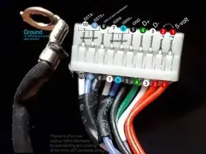
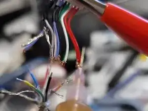
    • Fixers replacing the entire cable may choose to solder a new JST GH connector to their new cable before disassembly, reducing the time the camera sits in pieces. (Reuse the original ground wire for the cable sheath/shielding.)

    As of September 2021, per Logitech StreamCam support: “Unfortunately, the mount and a detached USB C cable is not in production for our spare parts services.” So, despite the cable being modular, your only recourse for repair is to harvest the cable from a scrap camera, repair existing damage, or craft your own replacement.

    Brian -

    This is the pinout, from right to left in your image:

    Red x2 (5V)

    White (D- standard colour)

    Green (D+ standard colour)

    Black (GND)

    Blue SSRX+

    White SSRX-

    Black (GND)

    Blue SSTX+

    White SSTX-

    Hope that helps people!

    Joshua Veitch-Michaelis -

  4. VU4eHJYS5lojViht
    VU4eHJYS5lojViht
    jwB6QRSuri4LGbXs
    • 2024.03.04 Warning: Due to reports and my own experience of failure to achieve 60fps, I believe the SSTX and SSRX pinouts are inverted. I will experiment and update the guide ASAP with any corrections.

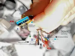
    • 20240310: swapping 10 with 9, and 7 with 6 (polarity reversals) has given me 1080 60fps on Win 10 with Logitech Capture, but now my Linux PC doesn't recognize the camera.

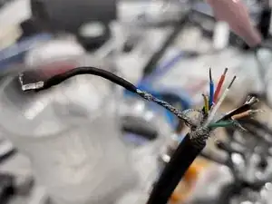
    • In this guide, a 6-foot USB-3.0 extension cable (female and male type-A plugs) was the donor part. The female plug was cut off with several inches of cable, so that it could be repurposed; the male end and cable is used in this repair.

    • Researching USB 3.0 cable wiring, SSRX+ and SSRX- appeared mapped to yellow and blue, respectively. With the donor cable used here, however, continuity testing proved unexpected wire color deviation. SSRX+ and SSRX- as pictured in the accompanying donor cable image yielded a successful camera repair.

    • If the distal USB-C plug of the original cable is the only defect, you may alternatively or preferentially choose to replace it with a USB 3.0 type-C or type-A plug -- rather than replacing the entire cable. You can then retain the sturdy original retention collar and greatly simplify the soldering work.

    Hi and thanks for the guide! I wonder if this pin layout is right, I opened the Type C plug of the cam to find this:

    Red covered cable on A2 (white), A3 (blueish) and the two strains of the green covered cable on B10 (blueish) and B11 (white). I think this would invert the polarity of the TX and RX cables in your sketch but also which cables belong to TX and RX, right?

    Am I mistaken? Thanks for the help!

    Mirko Förster -

    I now think the pinout pictured above is wrong. That wiring let me used the camera at 30fps on Linux and Windows 10, but no 60fps. Leaving TX and RX pairs where they were diagrammed, but switching the polarities has allowed me to get 1080 60fps on Windows 10 with Logitech Capture, but now my Linux PC doesn't recognize the camera. I've still got more investigating to do, unfortunately.

    Brian -

    HI Brian, Great guide. I have one of these cameras with a damaged usb plug, I was hoping to attempt a repair. I have peeled the usb plug on mine apart and uncovered the PCB and terminations, does this help unlock the Pinout detail required to make a full repair?

    I can share some images, let me know if it would be of use to see them.

    I was going to attempt to splice rather than open up the camera. Any reason this would be a bad idea?

    shane hall -

    Hi, Shane. Yes, I'm interested to see any images of the peeled plug.

    When splicing, I'd still recommend opening the camera so that you can verify continuity from end to end, with no short-circuits to neighboring wires. Unless, of course, you're completely confident that your distal soldering is discrete and clean. If you're capable of the splice, I think you'll find opening/reassembling the camera to be short work -- and worth your while to be doubly sure that each pin's continuity is what you're expecting.

    Brian -

    After doing some google searching on the PCB name "Dali V04 201" I have stumbled across some info which may be of use.

    Pin-out BA and BB on a USB-C plug? : r/diyelectronics (reddit.com)

    "The original connector has a 5.1 kOhm pull-down resistor on the CC1/CC2 lines."

    This is the pinout detail I will attempt to use

    PCB Label: Wire pair: Wire color connected /

    VB - Red

    VB - Red

    G Pair 1 (Green foil) Grounding of pair 1

    BA (B10) Pair 1 (Green foil) Grayish

    BB (B11) Pair 1 (Green foil) White

    A2 Pair 2 (Red/Pink foil) White

    A3 Pair 2 (Red/Pink foil) Grayish

    G Pair 2 (Red/Pink foil) Grounding of pair 2

    A6 Pair 3 (Gray shielded) Green

    A7 Pair 3 (Gray shielded) White

    G Pair 3 (Gray shielded) Grounding of pair 3

    shane hall -

    I haven't had time to troubleshoot the twisted pairs, but I'm interested to learn how your splice works out, Shane.

    Brian -

    Hello, thanks so much for putting this together. I'm about to attempt this repair myself too, where did you get to with the pin layout? Are the images accurate or do I need to switch 10 with 9 and 7 with 6? I'm only replacing the USB-C connector with a USB-A one myself.

    Greig Skivington -

    I haven't yet looked into it further, so there's no new update beyond my Mar 10 one:

    If you're using a Windows PC with Logitech Capture, making the indicated swaps is probably the way to go.

    Brian -

  5. i6bVLTEJ6TTeY2Os
    i6bVLTEJ6TTeY2Os
    lj1aYNR2rWuuCvIT
    • Soldering is the most challenging task of this repair, but beyond the scope of this guide. Always ensure adequate ventilation, and use respiratory and eye protection.

    • The soldering results displayed in this guide are amateur and achievable by those with intermediate skills. Practice and patience are the key elements of success.

    • After soldering, use a multimeter or stand-alone continuity tester to verify that each pin of the connector has continuity with only the expected USB plug contact, as mapped in the previous step.

    • Each twisted pair of the cable has its own shielding that must be joined and linked to the black wire of board connector pin 8.

  6. TOkjNARPlkXW6fDF
    TOkjNARPlkXW6fDF
    yMklYKAIoF4hOVod
    2rqStghsQWOZSQwY
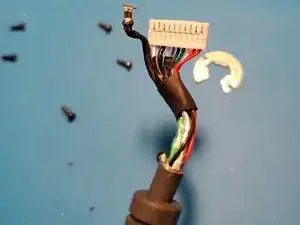
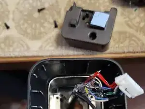
    • Three screws hold the inner block. Removing this eases the task of threading through the board connector and insulated soldering work.

    • Not pictured is application of insulation to the soldered connections. This is necessary to prevent short circuiting and equipment failure. Options include heatshrink tubing, liquid electrical tape, or hot glue, among other approaches.

    • Cable retention and strain relief is created with hot glue as pictured. Sugru is recommended as a clean, strong, and aesthetically pleasing alternative.

    • The hot glue was applied two-fold: within the housing (through the rear cutout), then at the C-clip flange. The C-clip was screwed down atop the second glue application while it was still cooling.

    I had my Stream Cam essentially do the same thing except the whole usb-c male end snapped clean off. Logitech said I was not under warranty so I just let it go and forgot about it. Fast forward to now and I want to fix it more for fun I guess. I stumbled upon this connecter that looks eerily similar to the one Logitech used on the Stream Cam looking at it from your guide. At least the connecter end. Does this look like the same connector to you? I don't know much about re-wiring cables and wires so I'm not sure it would even work even if it was the same fitting. Here's the link. https://www.gorite.com/dawson-canyon-usb... ; If not, ill need to track down sautering iron.

    simon -

Conclusion

To reassemble your device, follow the initial instructions in reverse order. Pat yourself on the back for keeping this camera out of the waste stream!

Brian

Member since: 12/08/16

450 Reputation

33 comments

Hi Brian, thanks very much for this guide. Do you know where I can get a replacement cable for the cam? I haven’t been able to find any online? Thanks again.

Z

zaskif -

You’re welcome, Zaskif. I made a comment attached to the guide, but it looks like it’s hidden… I reached out to Logitech support, and they confirmed that they don’t sell a replacement cable for the StreamCam. It’s a crazy bad look for Logitech, since it appears damage to the distal USB-C connection is a relatively common issue (that’s why I made the guide in the first place). “Support” said the only recourse is to replace the whole camera.

I’m in the middle of using a continuity tester to determine the pinout of the header, as it corresponds to the USB-C pins. Then I’ll wire the header plug to a DIY breakout female USB-C port, so I can use a USB C-to-C male-to-male cable I got for less than $10 online. Until I can succeed, I think the only other way for an accessible repair is to get a “for parts” camera that’s damaged in a different way, so that you can harvest its intact cable.

Brian -

I see, I’ve just seen your comment. Logitech has obviously thought this through! Such a shame they don’t even sell replacement parts for the cam on their website, knowing very well this is a common issue. I will probably end up selling it as “damaged”. Thanks very much for your response.

zaskif -

Hi Brian, any luck with the cable pinout? I’d be interested as i have a USB C Female part I could use as you described.

Manuel Guijarro -

No, Manuel, not really. I think I traced the board connector pins to the male USB-C end pins, but I don’t know enough about electronics engineering to know whether the Logitech cable has special resistors or other circuitry embedded in the distal plug. I’m anxious that assuming otherwise will fry the camera or a computer’s USB port. So, I’m on the lookout for a camera for sale that’s damaged in a different way, so I can harvest the intact cable, do further testing, repair and give an update here.

Brian -

Manuel, if this is still a pending project for you, I've now updated the guide with graphics and instructions to repair the camera with an inexpensive donor cable. Cheers.

Brian -

Hey brian, do you know any links where I can find a replacement for the cable? I’m not well known in these kinds of stuffs but it looks like streamcam uses jst gh connector that is connected in the webcam. Am not really sure what kind of jst gh connector the streamcam uses. I haven’t disassemble the stream cause I don’t wanna take any risk if I don’t have a cable replacement yet before fully disassmebling the webcam. It looks like I can use a jst gh to usb type c cable, I found bunch of replacements in alibaba, but I don’t know what specific cable I need to buy. Thank you in advance if you response to my comment

sauce -

I don’t have a replacement source, unfortunately. I don’t know what you mean by “jst gh”. My photos show what the connector inside the camera looks like… So, while the distal end of the cable is a USB Type-C, it doesn’t necessarily mean there’s not more to it. Like I said to Manuel, I don’t have the electronics expertise to reverse engineer whether there are some non-standard SMD components at the distal plug, despite being able to tease out the continuity from the distal pins to the proximal board plug/wires.

Brian -

Hey, Would you know where to buy the part of usb c that is needed to stop those cables?

malcoEM -

I got this working :) I used a USB-3 A connector because it's more convenient. There are no resistors required on the plug end, or at least my camera works fine without any.

Ideally buy a new USB3 connector (eg UP3-AV-4-CM). Splicing an old cable is not a good choice, because you'll have poor shielding and you have to make 9 extremely fiddly splices and isolation. Just buy a new connector, they cost a dollar. There are 9 signals. If you look at the JST end (in the camera), the pinout is the same as a USB-3A connector:

Red x2 (5V)

White (D- standard colour)

Green (D+ standard colour)

Black (GND)

Blue SSRX+

White SSRX-

Black GND

Blue SSTX+

White SSTX-

I double checked this by continuity checking my broken USB-C connector (the housing fell off but the contacts were still fine). You should too, but the important thing is that you get the USB-2 side correct with no shorts. The other cables are differential so provided you don't connect them to each other, wrong wiring shouldn't blow up the camera.

There are three signal pairs. The USB2 D+/D- and the USB3 Superspeed Transmit and Receive. The sheathed SS pairs also have their ground wire (uninsulated). USB2 is easy to identify because it's green/white. You can double check the SSRX and SSTX against the USB-C connector that broke, but this pinout works for me. I followed a guide by CONEC on how to manage the cables. Basically you should crimp the cable sheath to the USB-3 plug.

Joshua Veitch-Michaelis -

Thanks for your pinout listing of the JST connector, Joshua. I finally got around to soldering tonight, and I used it to pair the JST pigtail to a small USB-C female breakout board. Not pretty, but worked as a proof-of-concept so I could verify function, take photos, and work to update the above guide with more substance. Cheers.

Brian -

When I get a new connector ordered, I'll add the re-assembly steps to the guide.

Joshua Veitch-Michaelis -

Please let me know when you add this to the guide, I would like to replace just the usb-c end but am having some trouble removing it as it is shielded. Also not sure which one to buy from Amazon.

Bryan Zick -

For future reference, I also repaired the connector on one of these cameras.

I used a USB-C connector (though I should have thought about the USB-3 connector used by the previous commenter, as it is way more convenient). This is the connector I used: USB-C connector.

I simply cut of the old connector (leaving about 3-4cm of wire attached) and striped off all the covering/casing/shielding/glue so the PCB was showing. Now you can trace the different wires to the different connector pads on the PCB). The connector pads on the original PCB have labels of A2, A3, A6, A7, B10, B11, Vin, GRD. These correspond to the same labelled PCB pads on the above new connector.

Now it's just a matter of matching and soldering on the correct wire to the correct PCB pad on the new connector. The two red wires both attach to the Vin pad. Three different ground wires (Black wire and the two bare/unshielded wires from two of the twisted pair wire bundles) attached the the GRD pad.


Once everything was soldered up and I checked it was working, I wrapped tape around the PCB to protect it (I used Kapton tape because it is really thin and sticks well). The I reused the original metal casing(s) to cover the PCB and held it all together with heatshrink.

Richard Piola -

Hi, do you happen to recall which color of wire go to which pad? Thanks so much!

Kalix Jace -

I have not soldered the wires yet, but mine where:

Aluminum sheilding

green cable = A6 = D+

white cable = A7 = D-

Aluminum sheilding

violet/light blue = A3 = TX-

white = A2 = TX+

Bare wire = G = ground

Image of above

Aluminum sheilding with green plastic coating

Bare wire = G = ground

white = B11 = RX+

violet/light blue = B10 = RX-

Two red wires = V+

Black wire = GND = ground

Image of above

Tobias -

Hello Tobias.

Thanks for the detailed information!

I've tried to solder the wires as you described but it doesn't seem to work for me. I guess I'm doing something wrong.

Did you solder yours? Everything worked

JV Lobo -

so I had a slightly different experience, basically the same thing as above, except the shielding colours on the TX and RX wires were swapped (the bare wires of course also lead to ground in my case, BUT specifically don't share continuity with the black wire). continuity testing with my multimeter provided this layout on the USB-C pins:
STNDRD:\GND\TX+\TX-\VBS\\\\\\\\\\\\\\\\\VBS\\\\\\\\\GND

SHIELD:\\\\\GRN\GRN\\\\\\\\\\\\\\\\\\\\\\\\\\\\\\\\\\\\

COLOUR:\BLK\WHT\BLU\RED\\\\\\\\\\\\\\\\\RED\\\\\\\\\BLK

\\\\\\\\\*\\\*\\\*\\\*\\\*\\\-\\\-\\\*\\\*\\\*\\\*\\\*\

\\\\\\\\\*\\\*\\\*\\\*\\\*\\\*\\\*\\\*\\\*\\\*\\\*\\\*\

COLOUR:\BLK\WHT\BLU\RED\\\\\WHT\GRN\\\\\RED\\\\\\\\\BLK

SHIELD:\\\\\SLV SLV\\\\\\\\\\\\\\\\\\\\\\\\\\\\\\\\\\\\

STNDRD:\GND\RX+\RX-\VBS\\\\\D+\\D-\\\\\\VBS\\\\\\\\\GND

just to be clear, i think the shielding or wire colours might differ between production dates or something, because I can't find any consistent reports.

sorry about the backslashes, apparently extra whitespace gets deleted even in code blocks

Maxwell Letterlock -

Hey guys,

I have the same problem and bought USB-A 3.0 to replace the USB-C connector.

My question is: Where do i solder the BARE ground wires of RX+/RX- and TX+/TX- because there are 2 of them and only 1 pad on USB-A 3.0?

Btw, great advices and great community, you helped me alot so thank you very much!

P.S

My wire layout is the same as in post from Tobias (above).

aleksa25x -

The two different wire strands from the RX+/RX- and TX+/TX- cables (their drain wires) should both go to the GND_DRAIN connection on the USB-A connector.

Source: Each shielded pair includes its own drain wire, one for each pair; however both drain wires are attached to a single pin on the connector.

This worked for me and I now have the device functioning again with a USB-A 3.0 cable. Hope this helps!

AsciiJakob -

To get this working over usb you only need to buy a usb 3.1 type c male connect £3 on ebay the 4 pads G D+ D- V+ on the connector G black wire D+green D-white wire and V+ the two red wires the green and white wires are in the aluminium sleeving and the pair of wire in the green and red sleeve are not needed simple

Daniel Bailey -

You got usb2 connection. Camera will work, but no 60 fps.

Oleg Vin -

Type of connector that used inside camera is Micro JST GH 1,25 10P
Link to ali - https://aliexpress.ru/item/4001175655443...

So you can use any USB 3 cable and solder it to connector.

Oleg Vin -

My streamcam cable is found broken and have no use too ☹️

form7john-hello -

I updated the guide after your comment! There are now many more details to guide repairs.

Brian -

Hi Brian, thanks for helping out everything is working. there is one problem, it only works 30 frames per second. The computer writes connect to USB 3.0

Роберт Хакимов -

Did you replace the cord or only the USB plug? What plug type did you use? If you did soldering, did you verify continuities afterward?

Brian -

hi. I replaced only the 3.0 type a connector. I checked all connections. everything is fine

Роберт Хакимов -

Not sure. Can you 100% verify that the SSRX and SSTX twisted pairs were identified and grounded correctly? You're certain that it's plugged into a USB 3.x port?

Brian -

hi, in one photo you combined the gnd of a twisted pair and connected it into a groud. and the other one in the diagram is different, which one is correct

Роберт Хакимов -

I don't see what you mean about the difference. I do, however, recognize it is confusing that there are different grounds -- one for the entire cable's jacket/sheath; "pin 5"; and "pin 8" of the diagrams -- 8 being solely for the combination of twisted-pair sheaths. IIRC, pin 8 has separate continuity from the cable jacket and pin 5, though they're each a "ground". I'm not sure when/if it makes a practical difference, though.

Brian -

I need to review the SSRX and SSTX routing/pinouts. I haven't used the camera much beyond verifying it worked; looking closely tonight, it appears that the high-speed data isn't working, not recognizing the USB 3.x.

Brian -

I had my Stream Cam essentially do the same thing except the whole usb-c male end snapped clean off. Logitech said I was not under warranty so I just let it go and forgot about it. Fast forward to now and I want to fix it more for fun I guess. I stumbled upon this connecter that looks eerily similar to the one Logitech used on the Stream Cam looking at it from your guide. At least the connecter end. Does this look like the same connector to you? I don't know much about re-wiring cables and wires so I'm not sure it would even work even if it was the same fitting. Here's the link. https://www.gorite.com/dawson-canyon-usb... ; If not, ill need to track down sautering iron.

simon -