Introduction
This guide details the steps involved in replacing the switches for both your left and right mouse buttons with new ones. This might be necessary if your current switches are damaged or if you prefer a quieter option.
---------------------------------------------------------------------------------------
I took over this guide from Reddit to preserve it.
FULL CREDIT GOES TO u/Spook_485
-
-
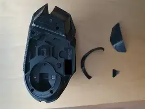
First off, remove the magnetic cover and remove the 3 stock skates. You can reuse them if you pull them off carefully. Logitech skates consist of the actual Teflon skates and a second layer of foamy adhesive. Make sure you pull off both still attached to each other.
-
-
-
Start at the back and just clip the whole cover open. Don't be afraid to use a little force. Either use a clipping tool, or just use 3 fingers and your fingernails to grab into the gap and pull it off.
-
-
-
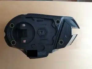
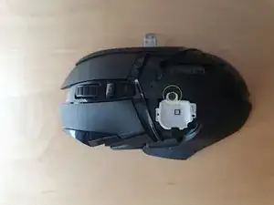
Next remove this screw (it's hidden deep, you will need a thin screwdriver to reach it)
-
And this one, This will allow you to remove the top LED cover.
-
-
-
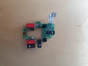
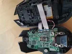
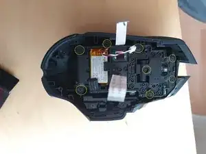
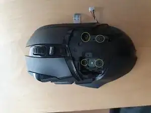
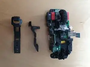
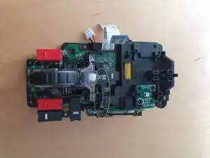
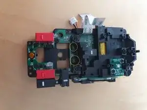
Remove these 4 screws which attach the 2 main buttons to the rest of the module. The right mouse button will fall out, while the left one will stay in place, just put the right one aside for now, you can leave the left one hanging loose. After removing these 4 screws, just pull out the whole internal module.
-
-
-
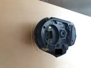
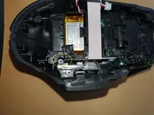
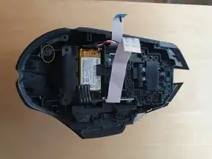
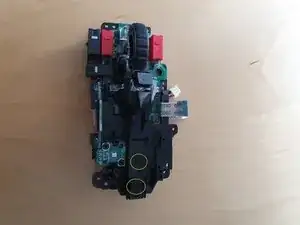
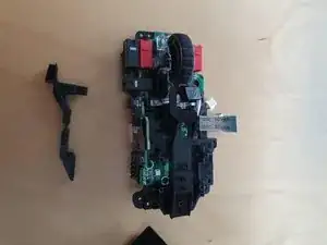
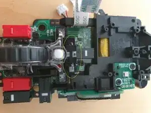
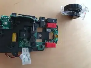
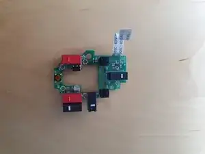
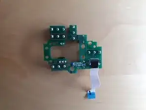
Pull out this plastic bolt which holds the scroll wheel module in place. I suggest you use something sharp to push at the bolt from the one end and pull it with your fingernails from the other side at the same time. It will require some force. After it's out, you can simply lift the whole scroll wheel module off the PCB.
-


To reassemble your device, follow these instructions in reverse order.

One comment
Thanks for the guide, i used some isopropanol to clean the switches instead of chaning them as i had a problem with the right one and now it works flawless.