Introduction

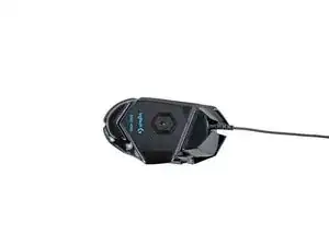
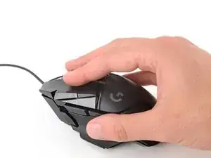
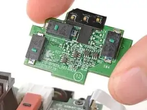
Use this guide to replace the side buttons board in your Logitech G502 Hero wired gaming mouse.

If your side buttons aren't working, are sticking, or aren't clicking all the way, you may need to replace the side buttons board.

  1. tElbjKhCJLc43yfA
    • Before starting your repair, unplug the mouse.

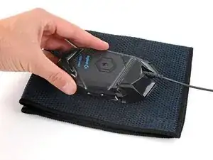
    • Throughout your repair, it may be helpful to lay your mouse on a soft cloth to stabilize it and prevent damage while you work.

  2. 3BWmpkWhErktyNSh
    3BWmpkWhErktyNSh
    wuouIXZ5r5Sax6Uq
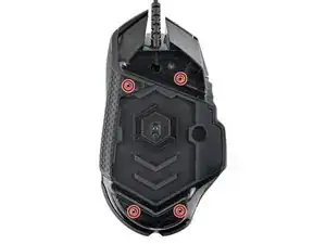
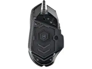
    • The feet are secured to the bottom of the mouse with adhesive. In order to cleanly remove them, the adhesive needs to be thoroughly heated.

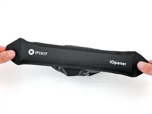
    • Heat an iOpener and lay it on the mouse feet for one minute to heat the adhesive.

    • Alternatively, you can use a hair dryer on the Low heat setting to soften the adhesive.

    • If you're using a hair dryer, only heat the feet a few seconds at a time or you may warp the plastic shell.

  3. vTIGFdruEKFciZsE
    vTIGFdruEKFciZsE
    Lj1I6AJPXvmYUsFr
    UYKpdWqqp4lctfZY
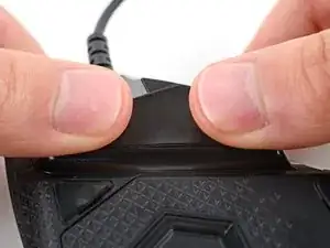
    • The feet have two layers—a rubberized one and an adhesive pad underneath.

    • If you're reusing the feet, be very careful not to separate the two layers or damage the feet.

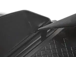
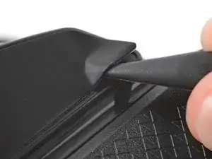
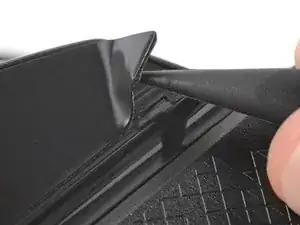
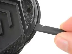
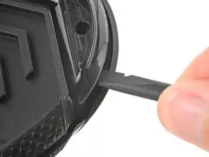
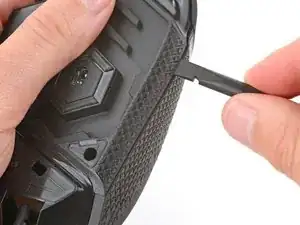
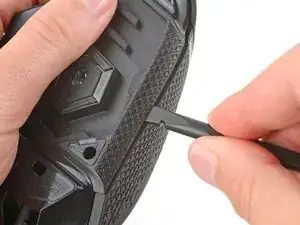
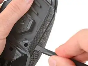
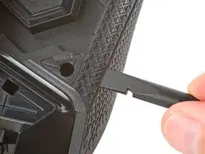
    • Carefully slide the point of a spudger under the large foot near the front of the mouse, making sure it goes under both the foot and its adhesive pad.

    • The foot recesses have a small notch that makes it easier to slide your spudger under.

    • Gently slide the spudger farther under the foot and lift until you can grip the pad with your fingers.

  4. iMrCnJZ5OvDGik2Z
    iMrCnJZ5OvDGik2Z
    NjrUF5HJOBC2HLNI
    MH2n66RPCnSrhvUy
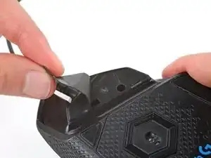
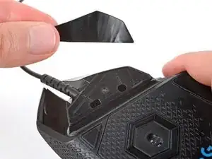
    • Peel up and remove the foot.

    • If the rubber layer separates from its adhesive pad, use the same process to remove the pad.

  5. oxnW2SgQZfEQkv16
    oxnW2SgQZfEQkv16
    3JE1qAWddsFtCE4X
    6tL6jAsOFxJseBuX
  6. yUPGTSiPEXGC3xi3
    yUPGTSiPEXGC3xi3
    asOCsVekYmlljkVZ
    LmkgsQlSD1flKUaB
    • To install a new foot:

    • If any of the feet got damaged during removal or separated from their adhesive pads, replace them.

    • Use a spudger to carefully scrape up and remove any remaining adhesive bits.

    • Use isopropyl alcohol and a microfiber cloth to thoroughly clean all adhesive residue from the foot recesses. Allow the surface to completely dry.

    • Remove the feet from their backing and firmly press them into place.

  7. pvxFg2xSbhIfFElP
    pvxFg2xSbhIfFElP
    I6anbwLs1YHgMcTR
    2ZY1G4giDkus5aHF
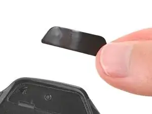
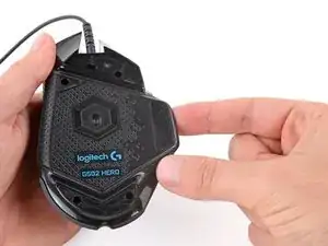
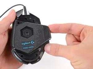
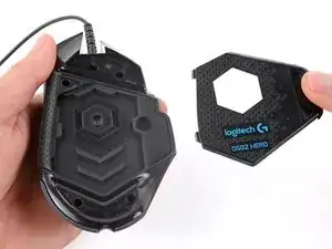
    • Lift the weight door by its tab and remove it.

    • If you have weights in the compartment, remove them.

  8. AyYVouEiCNEBGOOc
    AyYVouEiCNEBGOOc
    uMKO6XnBmYn2fqpQ
    • Use a Phillips screwdriver to remove the four 5.5 mm‑long screws securing the bottom shell.

  9. Sxvk1tUUb3nK6lrw
    Sxvk1tUUb3nK6lrw
    MQePBJMvIBYeWhBL
    lahBQHSCWYNZAxkK
    • Tight plastic clips secure the top and bottom shells. During the next few steps you should feel and hear "clicks" as the clips release.

    • Insert the flat end of a spudger between the top and bottom shells, near the back of the mouse.

    • Twist the spudger to unclip the shells.

  10. BZmvQIBeVOStIFkJ
    BZmvQIBeVOStIFkJ
    NRfVMF2EJWthDK5G
    ajxRCXCsJtIMM65F
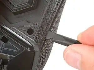
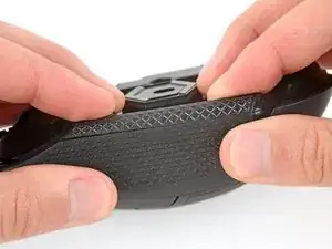
    • Insert the flat end of a spudger between the textured edge of the top and bottom shells, near the back of the mouse.

    • Slide the spudger towards the front of the mouse and intermittently twist, stopping near the screw hole.

    • Leave the spudger inserted for the next step.

  11. flqFfGfCmVUc3AsS
    flqFfGfCmVUc3AsS
    WXqKQbqOW3IKFoES
    XQMmNDPrStnE5sAW
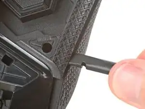
    • Push the spudger into the mouse and twist to unclip the shells.

  12. OfTLTUJLELNjNfvQ
    OfTLTUJLELNjNfvQ
    SlLYaNOwobjPKVIy
    Pa6b4JVVAVbuBHRo
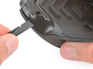
    • Insert the flat end of a spudger between the top and bottom shells, near the back of the mouse.

    • Slide the spudger towards the thumb rest and push in to unclip the shells.

  13. QwCxEsuMEL3mo5aS
    QwCxEsuMEL3mo5aS
    5DImO4Ea2cUDBXPj
    DuyH2vDPmPexDQAS
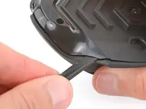
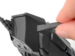
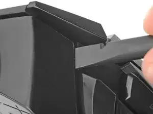
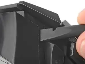
    • Insert the flat end of a spudger between the top and bottom shells, near the G8 and DPI shift () buttons at the front of the mouse.

    • Pry up with the spudger and push the shells apart to unclip them.

    • Unclipping this part of the mouse is tricky and may take a few tries. Be patient and don't pry too hard, or you may break one of the clips.

  14. W6qG6XPCUN4FwTfo
    W6qG6XPCUN4FwTfo
    FOCGG2WRsmyCTeFm
    QKrxJLhWZcMM3UvW
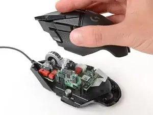
    • At this point, the shells should be fully separated. If they're not, repeat the previous unclipping steps with your spudger.

    • Lift the top shell straight up and remove it, making sure the main mouse cable stays attached to the bottom shell.

    • During reassembly, put the top shell back in place and work your way around the perimeter firmly squeezing the shells together to reengage the clips.

  15. i2XHNiwWweFyrncN
    i2XHNiwWweFyrncN
    vJPaYuypervPk6Ce
    HckgYHUVEkBBxbyq
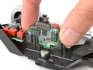
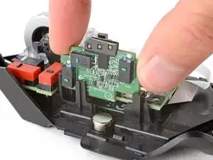
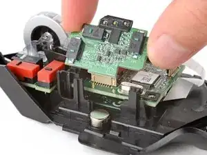
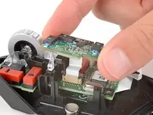
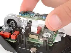
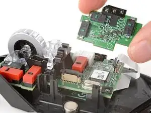
    • Gently lift the side buttons board straight up and out of its slot.

    • Don't try to fully remove the board yet, as it's still connected by a cable.

  16. PXxIAb34wKDGK2dt
    PXxIAb34wKDGK2dt
    pFZQACTiHM25eyVs
    GxrATuOJREvVuFJw
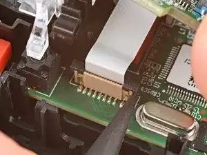
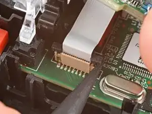
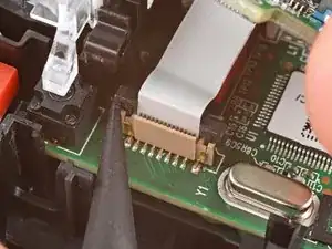
    • Hold the button board out of the way so you can access its connector on the motherboard.

    • Use the point of a spudger to push up on alternating sides of the connector's plastic latch until it's in the unlocked position.

    • You should feel the latch pop up into the unlocked position. Don't push too far, or the latch may come completely off the connector.

  17. ZhfqiF5FJ5TE6ueD
    ZhfqiF5FJ5TE6ueD
    W6SQYtpfcgBklMv2
    eeMZy5NYgn3IjWla
    • Gently pull the board straight up so the cable comes out of its socket.

    • The cable should come out easily. If you feel any resistance, push the latch up a little more and try again.

    • During reassembly:

    • Insert the cable into its socket so the blue tab is on the same side as the connector's latch.

    • Use the flat end of a spudger to push the latch straight down into its locked position.

  18. KDmU4cIuGqH4UNUq
    KDmU4cIuGqH4UNUq
    bXXnWrbYYTFWoIHG
    JUjyvH3r1OMRwcZZ
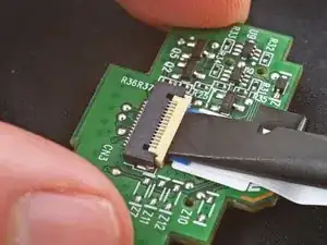
    • If your replacement board doesn't come with a cable, follow this step to remove and transfer the old one.

    • Set the board down on a clean, ESD‑safe surface so the side with the cable is facing up.

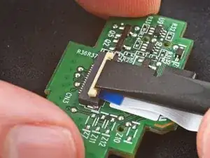
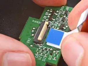
    • Use the point of a spudger to lift the locking flap on the ZIF connector.

    • Pull the cable straight out of its socket.

    • When installing the cable into the ZIF connector, make sure the ridged side is facing up.

Conclusion

To reassemble your device, follow these instructions in reverse order.

Take your e-waste to an R2 or e-Stewards certified recycler.

Repair didn’t go as planned? Try some basic troubleshooting, or ask our Answers community for help.
Spencer Day

Member since: 14/09/22

88286 Reputation

0 comments