Introduction
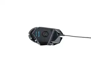
Use this guide to replace the motherboard in your Logitech G502 Hero wired gaming mouse.
If your mouse has erratic behavior or is not working, you may need to replace the motherboard. This should be a last resort after exhausting all other software and hardware diagnostics.
-
-
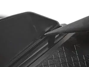
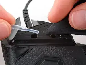
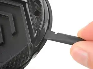
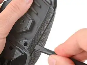
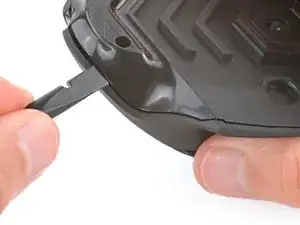
Carefully slide the point of a spudger under the large foot near the front of the mouse, making sure it goes under both the foot and its adhesive pad.
-
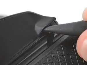
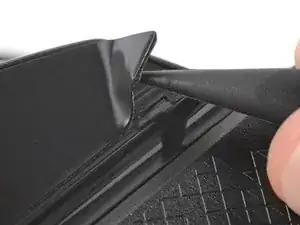
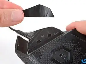
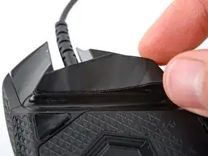
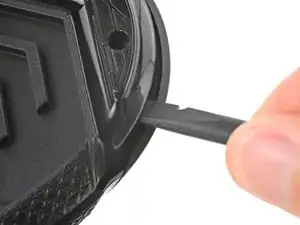
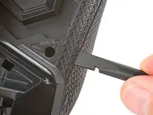
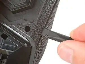
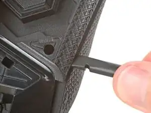
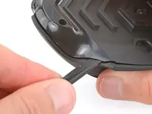
Gently slide the spudger farther under the foot and lift until you can grip the pad with your fingers.
-
-
-
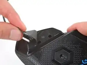
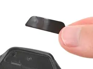
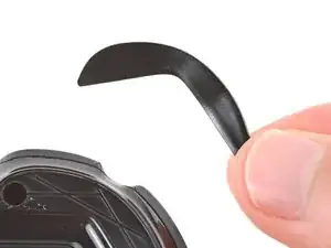
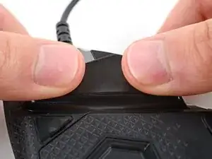
Peel up and remove the foot.
-
If the rubber layer separates from its adhesive pad, use the same process to remove the pad.
-
-
-
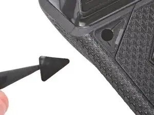
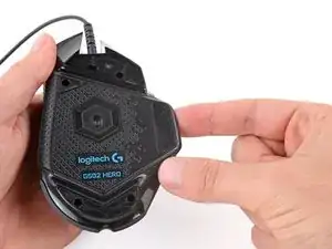
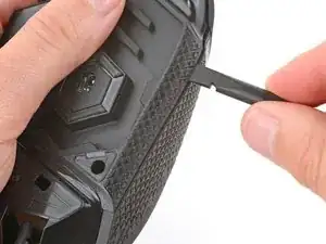
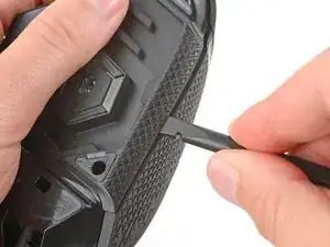
Use a spudger to carefully scrape up and remove any remaining adhesive bits.
-
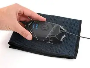
Use isopropyl alcohol and a microfiber cloth to thoroughly clean all adhesive residue from the foot recesses. Allow the surface to completely dry.
-
Remove the feet from their backing and firmly press them into place.
-
-
-
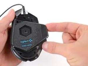
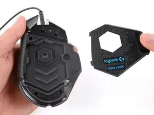
Lift the weight door by its tab and remove it.
-
If you have weights in the compartment, remove them.
-
-
-
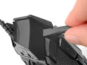
Insert the flat end of a spudger between the top and bottom shells, near the back of the mouse.
-
Twist the spudger to unclip the shells.
-
-
-
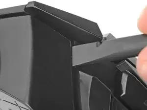
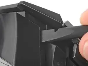
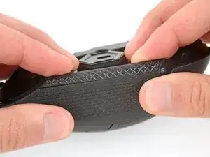
Insert the flat end of a spudger between the textured edge of the top and bottom shells, near the back of the mouse.
-
Slide the spudger towards the front of the mouse and intermittently twist, stopping near the screw hole.
-
Leave the spudger inserted for the next step.
-
-
-
Insert the flat end of a spudger between the top and bottom shells, near the back of the mouse.
-
Slide the spudger towards the thumb rest and push in to unclip the shells.
-
-
-
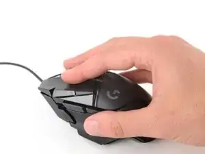
Insert the flat end of a spudger between the top and bottom shells, near the G8 and DPI shift (⊕) buttons at the front of the mouse.
-
Pry up with the spudger and push the shells apart to unclip them.
-
-
-
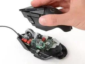
Lift the top shell straight up and remove it, making sure the main mouse cable stays attached to the bottom shell.
-
-
-
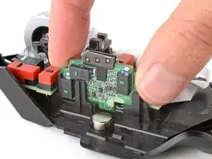
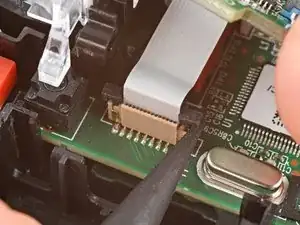
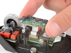
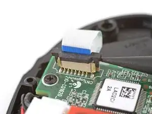
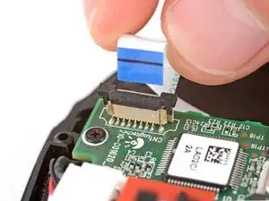
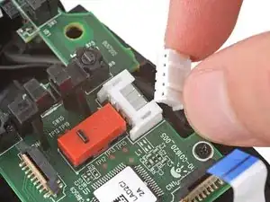
Hold the button board out of the way so you can access its connector on the motherboard.
-
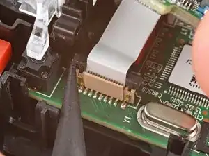
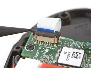
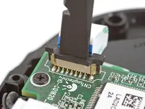
Use the point of a spudger to push up on alternating sides of the connector's plastic latch until it's in the unlocked position.
-
-
-
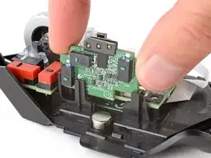
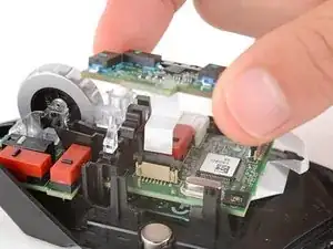
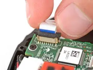
Gently pull the board straight up so the cable comes out of its socket.
-
Insert the cable into its socket so the blue tab is on the same side as the connector's latch.
-
Use the flat end of a spudger to push the latch straight down into its locked position.
-
-
-
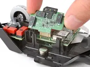
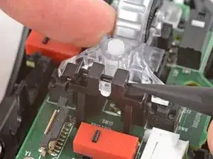
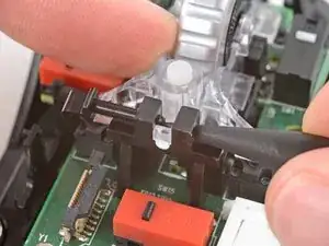
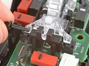
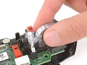
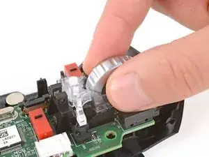
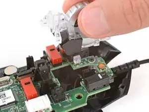
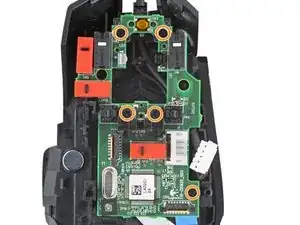
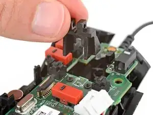
Use the point of a spudger to push out and remove the locking pin from the plastic scroll wheel support in the center of the motherboard.
-
-
-
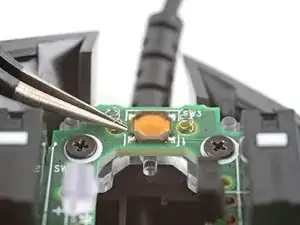
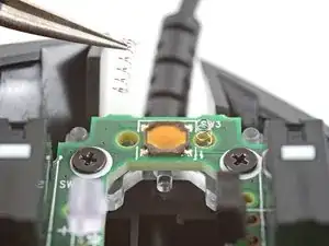
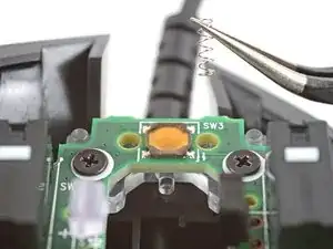
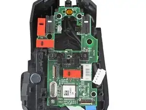
Use a pair of tweezers to carefully remove the two small springs near the front of the mouse.
-
-
-
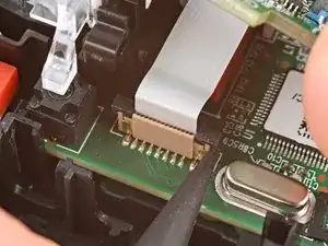
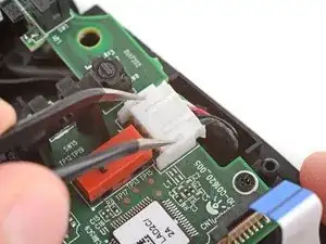
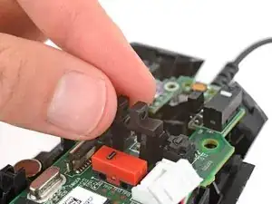
Use the point of a spudger to push up on alternating sides of the plastic latch on the connector near the bottom corner of the motherboard.
-
-
-
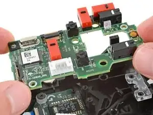
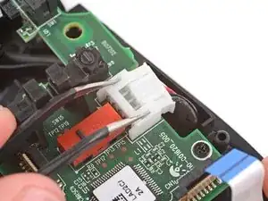
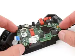
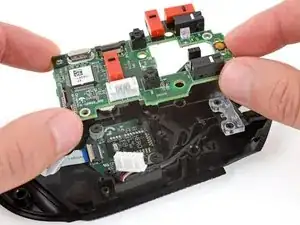
Insert each arm of a pair of angled tweezers into the cutouts on the outer edges of the mouse cable connector, located near the edge of the motherboard.
-
Use the tweezers to gently push the connector completely out of its socket.
-


To reassemble your device, follow these instructions in reverse order.
Take your e-waste to an R2 or e-Stewards certified recycler.
Repair didn’t go as planned? Try some basic troubleshooting, or ask our Answers community for help.
