Introduction
This guide demonstrates how to remove the logic board assembly from your Mac Studio (2023).
Tools
Parts
-
-
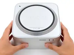
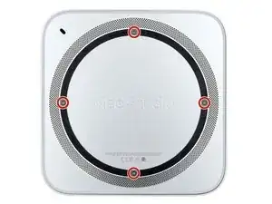
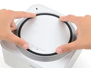
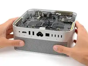
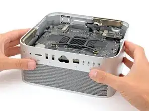
Flip your Mac Studio over and lay it down so the bottom faces up and the SD card slot and two front USB‑C ports are facing you.
-
-
-
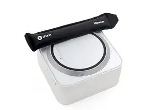
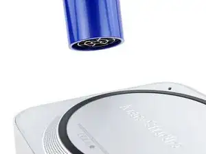
Heat an iOpener and lay it over one of the bottom cover screws for two minutes to soften the adhesive near the screw—this is where you'll insert a spudger in the next step.
-
-
-
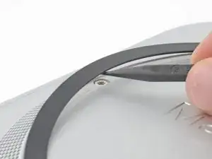
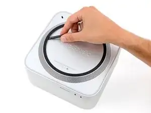
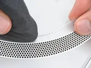
Insert the point of a spudger under the pad's inner edge, near the screw you applied heat to in the previous step.
-
Use the spudger to lift the pad and separate the adhesive.
-
-
-
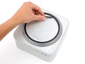
Insert the flat end of a spudger under the pad.
-
Slide the spudger under the entire pad to separate the remaining adhesive.
-
-
-
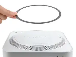
If the adhesive strips are still sticky, you can reuse them.
-
Use the flat end of a spudger and your fingers to scrape up and remove the old adhesive strips.
-
Use isopropyl alcohol and a microfiber cloth to remove the old adhesive residue.
-
Apply the new adhesive strips to the bottom cover and remove their liners.
-
Firmly press the bottom cover screw pad into its recess to secure it.
-
-
-
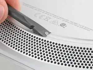
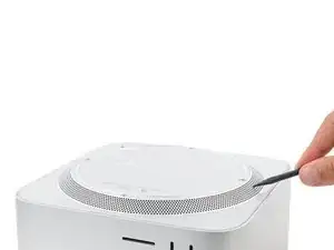
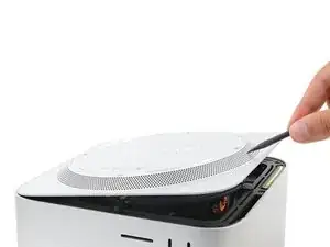
Insert the point of a spudger in one of the bottom cover's ventilation holes and lift the cover until you can grab it with your fingers.
-
Remove the bottom cover.
-
-
-
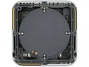
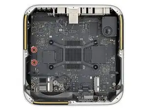
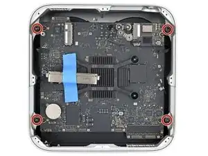
Use a T10 Torx screwdriver to remove the six screws securing the power supply:
-
Four 6 mm‑long screws
-
Two 7 mm‑long screws with washers
-
-
-
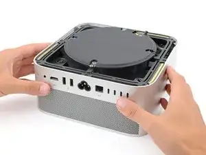
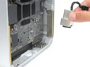
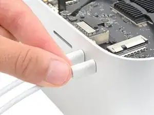
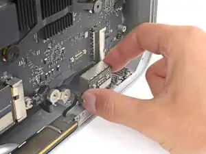
Firmly hold the power supply with one hand and lift up the edge near the power cord port.
-
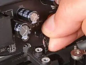
With your free hand, pinch the head of the power cord port connector to unclip it and pull straight down to disconnect the cable.
-
-
-
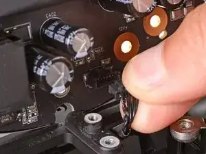
Carefully tilt the power supply away from the power cord port so it's at a 90-degree angle.
-
Keep the power supply tilted up for the next step.
-
-
-
With your free hand, pinch the head of the power supply connector to unclip it and pull straight away from the socket to disconnect the cable.
-
-
-
Use a T6 Torx screwdriver to remove the eight screws securing the internal frame:
-
Seven 5 mm‑long screws
-
One 4 mm‑long screw
-
-
-
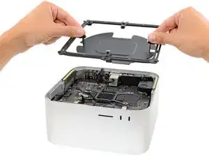
Slowly lift the internal frame straight up and remove it, making sure no cables get snagged.
-
-
-
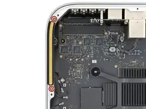
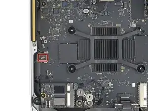
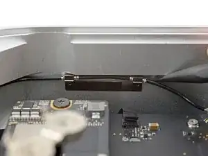
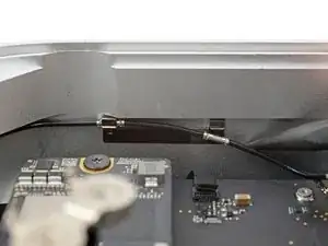
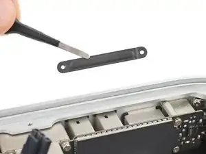
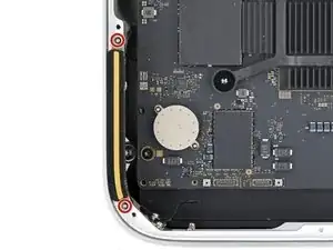
Use a T3 Torx screwdriver to remove the two 2 mm‑long screws securing the antenna cable cover.
-
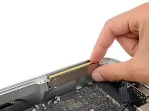
Use tweezers or your fingers to remove the cover.
-
-
-
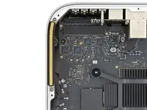
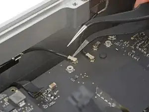
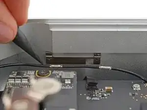
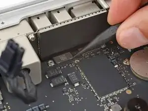
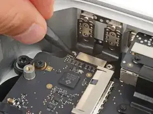
Insert one arm of a pair of angled tweezers under the metal neck of antenna 2's coaxial connector and lift straight up to disconnect it.
-
-
-
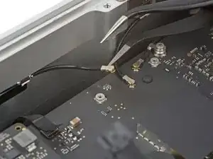
Insert one arm of a pair of angled tweezers under the metal neck of antenna 3's coaxial connector (next to antenna 2's connector) and lift straight up to disconnect it.
-
-
-
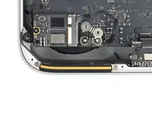
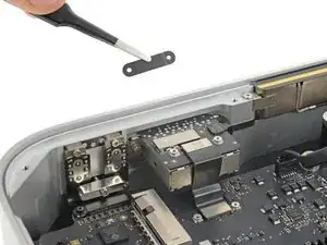
Use a T3 Torx screwdriver to remove the two 2 mm‑long screws securing the ethernet board cable cover.
-
Use tweezers or your fingers to remove the cover.
-
-
-
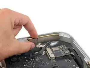
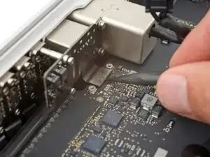
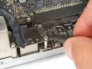
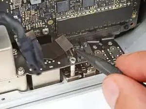
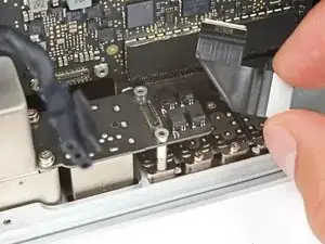
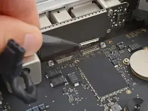
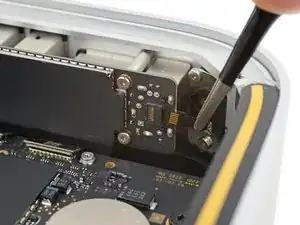
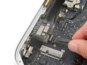
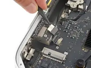
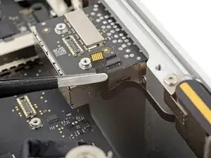
Use a spudger to pry up and disconnect the ethernet board cable press connector from the logic board.
-
-
-
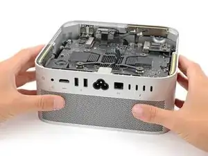
Carefully stand up your Mac Studio so the SD card reader and two front USB-C ports are facing up.
-
-
-
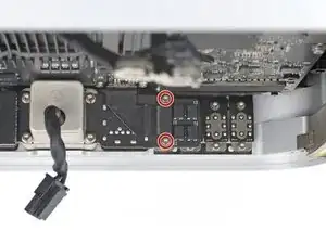
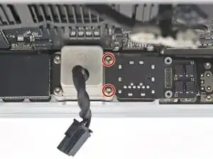
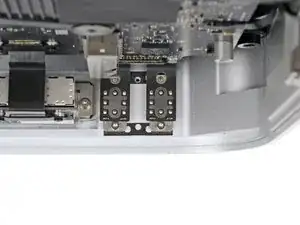
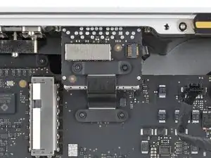
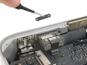
Use a T4 Torx screwdriver to remove the two 11 mm‑long screws securing the right side of the ethernet board and its cover.
-
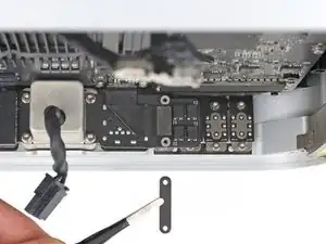
Use tweezers or your fingers to remove the cover.
-
-
-
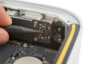
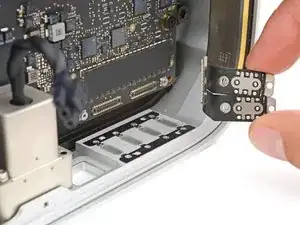
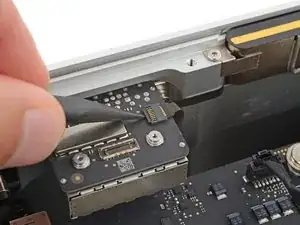
Insert the point of a spudger under the bottom right corner of the ethernet board press connector and lift up to disconnect it.
-
Remove the cable.
-
-
-
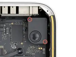
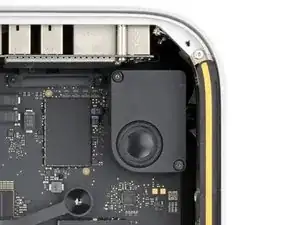
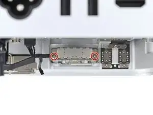
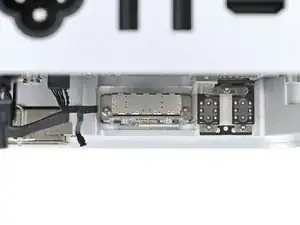
Use a T6 Torx screwdriver to remove the two 20 mm‑long screws (with washers) securing the ethernet board.
-
-
-
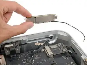
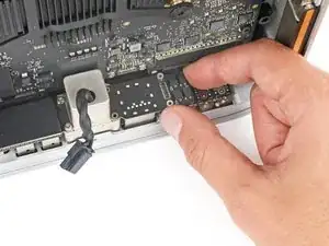
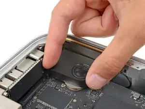
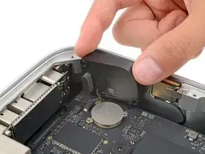
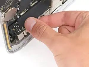
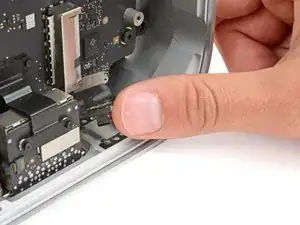
Lift the inner edge of the speaker and stand it upright so you can access its connector on the logic board.
-
-
-
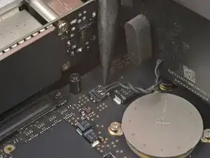
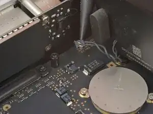
Insert the point of a spudger under the speaker connector's plastic head and carefully lift it straight up and out of its socket.
-
-
-
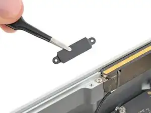
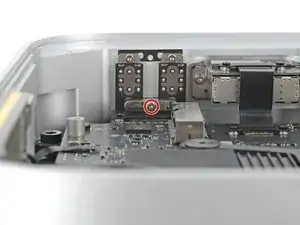
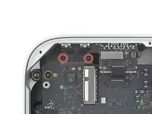
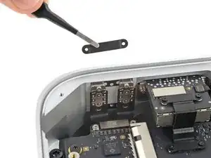
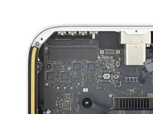
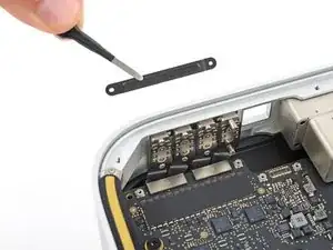
Use a T3 Torx screwdriver to remove the two 2 mm‑long screws securing the I/O board cable cover.
-
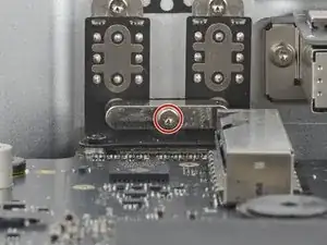
Use a T8 Torx screwdriver to remove the standoff screw just to the right of the cover.
-
-
-
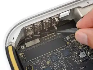
Use the point of a spudger or a clean fingernail to flip up the hinged locking flap on the power button cable ZIF connector, located on the outer edge of the I/O board.
-
Use tweezers to gently pull the cable straight out of its socket.
-
-
-
Carefully stand up your Mac Studio so the SD card reader and two front USB-C ports are facing up.
-
-
-
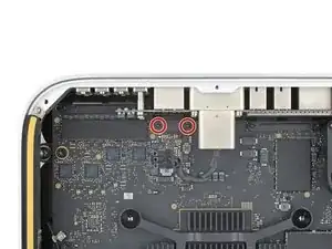
Use a T4 Torx screwdriver to remove the two 15.5 mm‑long screws securing the outer edge of the I/O board.
-
Use a T6 Torx screwdriver to remove the two 20 mm‑long screws securing the inner edge of the I/O board.
-
Partially tighten the four screws securing the board.
-
Lay your Mac Studio down and plug a cable into one of the ports to ensure proper fit and alignment, adjusting the port as necessary—the cable should be easy to insert and remove.
-
With the cable plugged in and the board in position, fully tighten all four screws.
-
Unplug all cables before continuing.
-
-
-
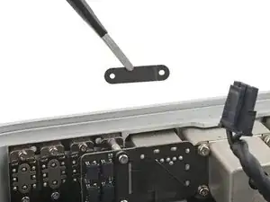
Use a T5 Torx screwdriver to fully loosen the 12.3 mm‑long screw securing the USB-C bracket.
-
Remove the USB-C bracket.
-
-
-
Use a T3 Torx screwdriver to remove the two 2 mm‑long screws securing the USB‑C port cable cover.
-
Use tweezers or your fingers to remove the cover.
-
-
-
Use the point of a spudger to pry up and disconnect the USB‑C port press connector from the logic board.
-
-
-
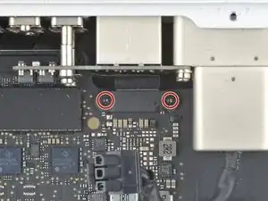
Use a T5 Torx screwdriver to remove the two 5 mm‑long screws securing the USB-C ports.
-
Partially tighten the two screws securing the top of the ports.
-
Put the USB-C bracket into place and partially tighten the screw that secures it.
-
Lay your Mac Studio down and plug a cable into each port to ensure proper fit and alignment, adjusting the ports as necessary—the cables should be easy to insert and remove.
-
With both cables plugged in and the ports in position, fully tighten all three screws.
-
Unplug any cables before continuing reassembly.
-
-
-
Use a T3 Torx screwdriver to remove the two 2 mm‑long screws securing the back Thunderbolt 4 port cable cover.
-
Use tweezers or your fingers to remove the cover.
-
-
-
Use a spudger to pry up and disconnect both Thunderbolt 4 cable press connectors from the logic board.
-
-
-
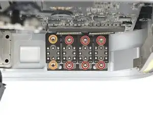
Use a T5 Torx screwdriver to remove the six 5 mm‑long screws securing three of the ports.
-
Use a T7 Torx screwdriver to remove the two 8 mm‑long standoff screws securing the remaining port.
-
Partially tighten all four screws on a set of ports.
-
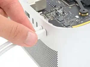
Lay your Mac Studio down and plug a cable into each port to ensure proper fit and alignment, adjusting the ports as necessary—the cable should be easy to insert and remove.
-
With both cables plugged in and the port in position, fully tighten the screws.
-
Unplug all cables before continuing with reassembly.
-
-
-
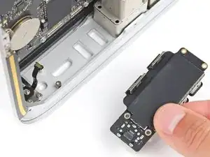
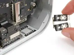
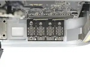
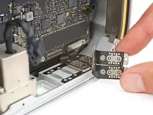
Use your fingers to lift the two inner or outer ports out of their recesses and remove them.
-
Repeat the process to remove the two other ports.
-
-
-
Use a T3 Torx screwdriver to remove the four 2 mm‑long screws securing the SDXC card reader cable covers.
-
-
-
Use the flat end of a spudger to pry up and disconnect the card reader cable press connector from the logic board.
-
Use the point of a spudger to disconnect the cable's other press connector from the reader itself.
-
Remove the cable.
-
-
-
Use the point of a spudger or a clean fingernail to flip up the hinged locking flap on the status indicator light cable ZIF connector, located on the right side of the card reader.
-
Use tweezers to gently pull the cable straight out of its socket.
-
-
-
Gently lay antenna 1 to the left of the heatsink, being careful not to strain its cable.
-
Secure antenna 1 to the logic board with a strip of painters tape.
-
-
-
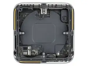
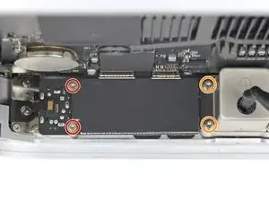
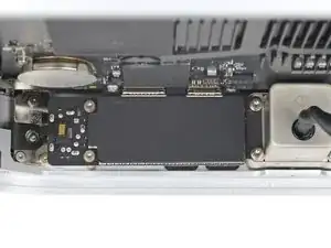
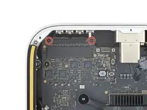
Use a T20 Torx screwdriver to remove the four 12 mm‑long screws securing the logic board assembly.
-
-
-
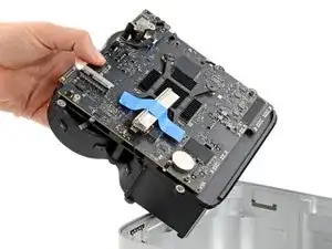
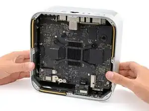
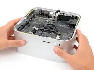
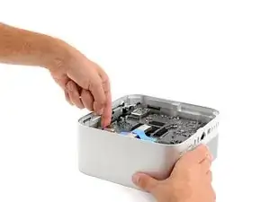
The assembly sits very snugly in its housing. Take your time and don't try to force it out.
-
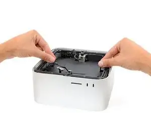
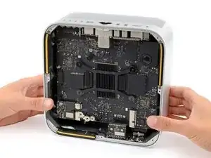
Firmly secure the housing with one hand.
-
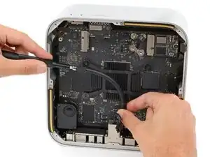
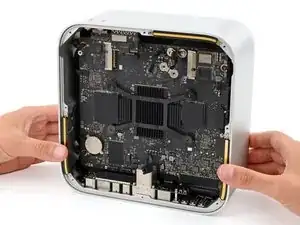
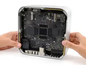
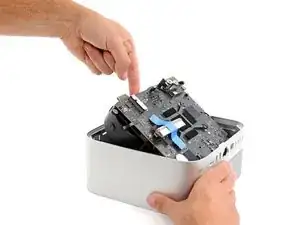
With your free hand, carefully lift the edge of the logic board assembly with the SSD modules until you can grip the fans. Slide the assembly towards the power cord cutout as necessary to help you lift it higher.
-
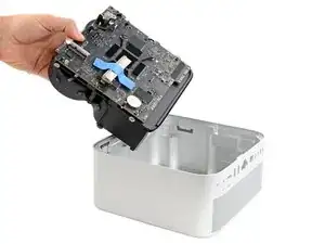
Grip the board and fans together and lift the assembly out of its housing.
-


To reassemble your device, follow these instructions in reverse order.
