Introduction

This guide will show you step-by-step how you can replace the display of your Lenovo Yoga Tab 3 Plus yourself.

In the process you could also swap the battery, if needed!

Below this guide I have attached the hardware maintenance manual for this Lenovo model for further reference.

Please don’t hesitate to comment on any mistakes I might have made in this guide, as this is the first repair guide I have ever written. 🙂

  1. VUPoUo3PJYnJxVc3
    VUPoUo3PJYnJxVc3
    JUK1jEGPLDBCuItZ
    C4MvhcYDOk54FTuR
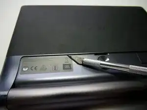
    • Turn the device over so that the screen is facing down.

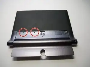
    • Under the big sticker are 2 small Phillips Screws. Remove those.

  2. TnVKWMGyvERcu2mC
    TnVKWMGyvERcu2mC
    gxHhS3uU6GNgt6kE
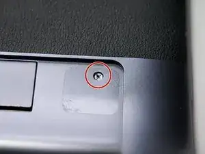
    • Unscrew the single Phillips Screw that is hiding underneath. It is covered by a small circular Sticker which you can poke through with your screwdriver.

  3. BW4upY44cGeBtYIC
    BW4upY44cGeBtYIC
    SFCgqKTbkhbR4QCR
    35NSIifKIKu3wEXp
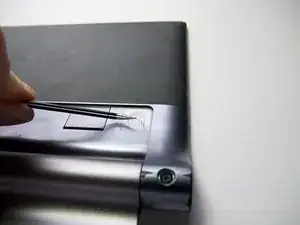
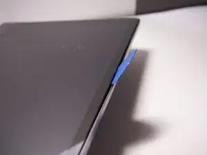
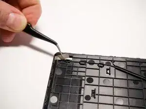
    • Start by inserting an opening pick between the plastic bezel and the screen at the position indicated in the first photo.

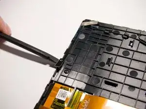
    • Then gently push the pick further into the device until you feel that you can pry safely without slipping. Work your way around the device and unclip the backplate from the screen (the direction doesn't matter)

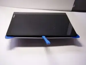
    • Use 2 opening picks at each of the upper corners to keep the backplate tensioned and use an opening tool to gently pry the backplate loose from the display.

    • Do not remove the backplate yet.

  4. WUYY33hlyf2XrWC6
    WUYY33hlyf2XrWC6
    vjfAlJ2KPA1HchtC
    • Turn the device over so the display is facing down.

    • With 2 hands, grab each upper corner and pull the backplate off the display.

    • Do not pull it apart as there is still a microphone and its cable glued to the backplate.

  5. Ei2IbJkQdevKeHSB
    Ei2IbJkQdevKeHSB
    WdvqQrQhKDeETVop
    EXGwxTx3Yl3rqKTi
    • Use a Spudger to remove the microphone that is glued to the backplate.

    • Remove the backplate.

    • Be careful not to loose the Power Button as it will probably fall out.

  6. 3CSbbfVpvpDJOg4S
    • It is not connected and can be lifted out.

  7. gCGxZgYaCXwYo3bO
    gCGxZgYaCXwYo3bO
    HrU2wSQZiJbWaAZE
    k3pFmTDWsjuuWEpH
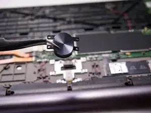
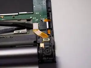
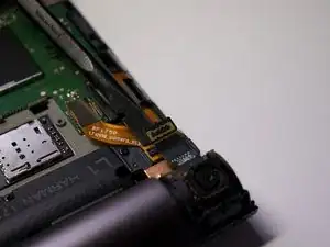
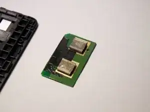
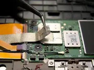
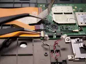
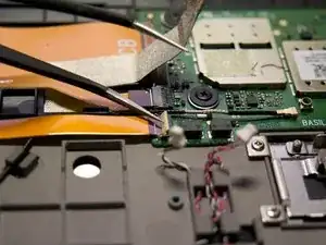
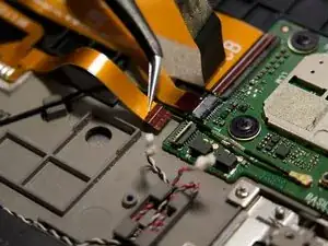
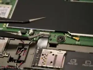
    • Use a Spudger to disconnect the two connectors for the camera.

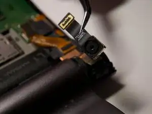
    • Lift the camera out of the device.

    • The camera is glued to the copper band beneath it, which in turn is glued to the device. Be careful not to damage the copper band.

  8. wlR41MiaV3yCXCRg
    wlR41MiaV3yCXCRg
    ASpjHPgGunwaCCFF
    XhvGYLGJXtZn3MCO
    • Gently unplug all 4 white connectors using a pair of ESD-safe precision tweezers.

  9. rYLK4HELQhuG2xrX
    rYLK4HELQhuG2xrX
    jBPuMPaVS6eBbr4K
    Vr4LnyKym2uY1E3L
    • Disconnect the 2 Antenna cables on the GPS-Antenna-Board.

  10. 52KxdvMHqWTaAXs2
    52KxdvMHqWTaAXs2
    QcqhwVMWLQKhfAZl
    CJjCqUWiXS2ZRKOC
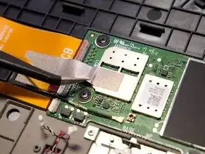
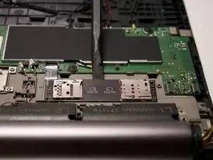
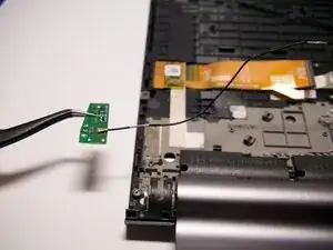
    • Start by inserting a Spudger under the corner indicated in the first photo and using it as a lever to pull the Board away from the device. Work your way around the small Board.

    • It is glued into place by 2 pads and some adhesive tape, so be careful not to break this small part. After removing it, make sure to "repair" both pads and the adhesive tape as much as possible, as you will need to install it to the new Display later.

  11. Y3553p3hUByfYMpJ
    Y3553p3hUByfYMpJ
    BFFQUAekiAeJAqMm
    i3PgBCvOJnK15hns
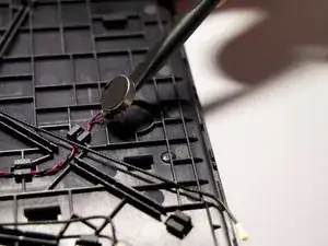
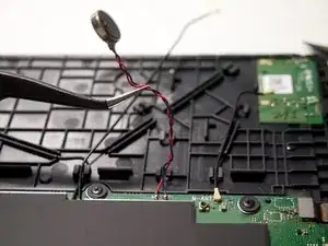
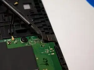
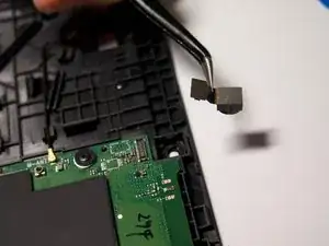
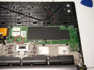
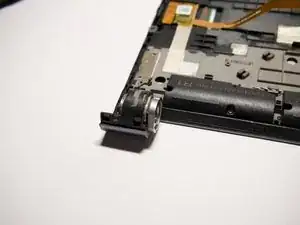
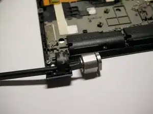
    • Lift the vibration motor up by prying it up using a Spudger. It is glued in place with strong adhesive.

    • Unclip the cable from the plastic.

  12. Tk1AcxXQM2ZSv2PV
    Tk1AcxXQM2ZSv2PV
    fwjbJdXJFRYLdNhT
    WmvLiBdmhktZnTMR
    • Using tweezers is a good method, but the tape also rips easily, so pay extra attention here.

  13. pJolvE25mlEeocwS
    pJolvE25mlEeocwS
    R1nviQRg2jNTcdgY
    cFZC4aQJiWpNewQr
    • Tweezers can easily damage the fragile ribbon cable.

  14. IIPb6VLNguRrEJWn
    IIPb6VLNguRrEJWn
    mKni2TXq1FJDdSeX
    brKSfNIBYEB4O5Kp
    • Tweezers can easily damage the fragile ribbon cable.

  15. t6gZsKPgOeeS5p2H
    t6gZsKPgOeeS5p2H
    l1121nOEpoZpgRbR
    rGQOXOCNdD1fbRKG
    • Tweezers can easily damage the fragile ribbon cable.

  16. xPwbCK56WkNchsXm
    xPwbCK56WkNchsXm
    y5aVXLdXEjCNSTF4
    • The ribbon cable can easily get damaged here, when pulled to hard.

    • It might be best to do this with your fingers instead of tweezers, as the fingertips won't damage the conductive mesh tape as much as tweezers would. Just make sure not to touch the adhesive part of the mesh.

  17. yaYsyFnCnkPPbN1W
    yaYsyFnCnkPPbN1W
    Rj44wQVwM2Vn3OtJ
    VBRQW3c1dQauRLId
    • Remove the 4 Phillips Screws.

    • Lift the bracket out of the device.

  18. mUNHSd1NYHD5J2JF
    mUNHSd1NYHD5J2JF
    fEYPNZaGkJDPFDvB
    • Gently lift the connector up using a Spudger.

  19. UBrgqKLPeNkkkF3p
    UBrgqKLPeNkkkF3p
    qOOTxD6vBqNxJAld
    • It is glued to the side.

    • Be careful not to slip and damage the very narrow ribbon cable.

  20. 6yQydKqJwcDYq6GO
    6yQydKqJwcDYq6GO
    GBJ3gCFOFimLSTco
    5dgYWCesN1WqKTZd
    • After this you can remove the part from the device.

  21. W3LByCoZOOLWQduo
    W3LByCoZOOLWQduo
    wU13QSnbhFDWgkLC
    • Use a Spudger.

  22. GYKfKYCLWOyNhmyo
    GYKfKYCLWOyNhmyo
    PD532iErJoMnHibj
    omZRK3CaBGWhGcjl
    • Disconnect the cable using your Spudger and tweezers.

    • It is glued in place with strong adhesive. Be careful not to rip off the metal plate at the end of the cable when lifting/pulling it up.

  23. XPEtvJPhANslFx32
    XPEtvJPhANslFx32
    4M6m5MWdxtng1dHn
    PD4rY4s2aimtMgXt
    • Use tweezers. Slightly bend the black ribbon cable upwards after this.

  24. koB4fyeY4mgBVPvB
    koB4fyeY4mgBVPvB
    pOuTfYyVC36gXneR
    X2nXtBGDURwSPued
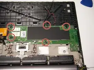
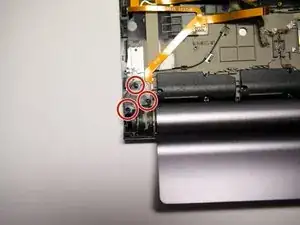
    • Use a Spudger and start in the middle of the top edge. push the Spudger under the board until you can lift it up slightly. Work your way to the right, until you can lift the Board up without bending it.

    • It is also glued in place with the same strong adhesive.

    • Try to avoid going near the ribbon cable with the Spudger.

  25. DxGRnUmNYkcOnQgU
    DxGRnUmNYkcOnQgU
    KsORTnWnwIpVOATY
    aDLflJPKHUnetUYt
    • Unplug the camera using a Spudger. Then simply lift it out of its hole.

  26. nRO1MQSFp5GUcQpa
    • Unscrew the 5 Phillips screws that are securing the motherboard.

  27. kULWDl3cHIwrgEsR
    kULWDl3cHIwrgEsR
    1NvVxSIrlHJo124j
    Hpg2vmyw4nSNBeTw
    • Use a Spudger.

    • Carefully bend the cable out of the way.

  28. nk54Cjbxb6xkXARW
    nk54Cjbxb6xkXARW
    KgRLKRExEI3mcScF
    GauXKg3fBLiC1L5N
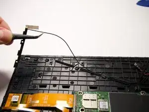
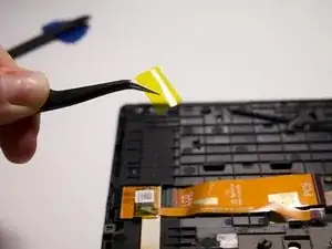
    • Remove the Part of the adhesive conductive mesh that is glued to the device.

    • Lift the Antenna up from the device using a Spudger, starting at the lower end. It is glued in place.

    • Unclip the cable connecting the Antenna with the motherboard.

    • Do not disconnect the Cable or the Antenna.

  29. MNFIKHMYVqsZFsnE
    MNFIKHMYVqsZFsnE
    UPXFCEwJEeP24CMW
    EcaUNfWYn1TgRAiE
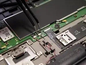
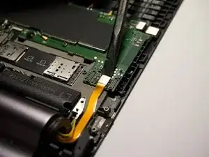
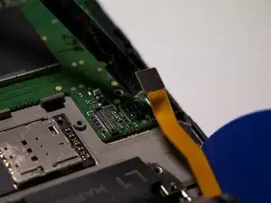
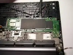
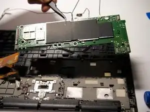
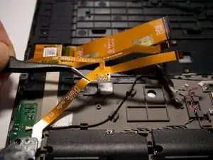
    • Start at the top of the motherboard as shown in the photo using a Spudger.

    • Work your way around the board as you gently pry it off the device.

    • Be careful not to damage the pads too much that are holding the motherboard down.

    • After lifting the motherboard out of the device, check that all pads are still on the motherboard and none are left in the device, as well as that they are not damaged. Otherwise try to repair them as much as you can.

  30. vs4pG4LUcIAZypZY
    • Remove the 3 Phillips screws that are securing the headphone jack in place.

  31. UY4JKbTHD5TD1NR5
    UY4JKbTHD5TD1NR5
    OkkMp2QFARJg6W2c
    bMGZsXi5EpYqoKlG
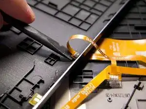
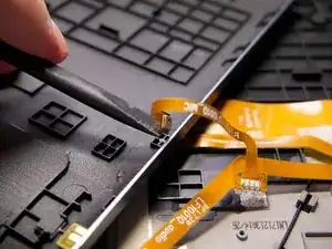
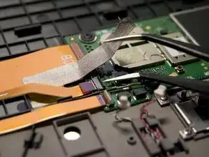
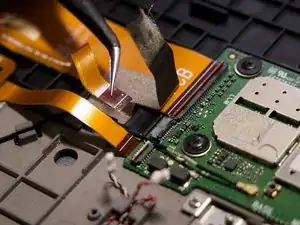
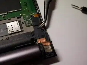
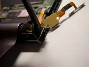
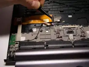
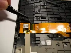
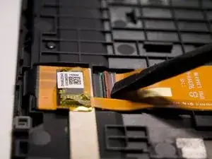
    • The ribbon cable is glued down beneath the connector. Gently use your tweezers and Spudger to lift it up.

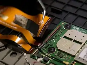
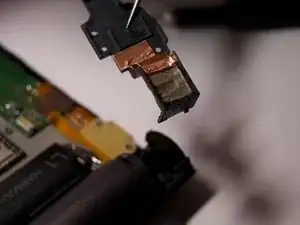
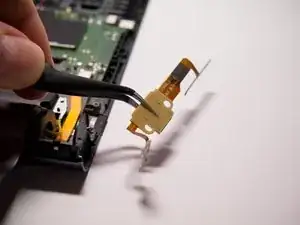
    • Lift the ribbon cable with the headphone jack and microphone out of the device.

  32. 4sEHmx6jrZDWNE5o
    4sEHmx6jrZDWNE5o
    lLdsj3YYfjJx2TYe
    lnHQ5ENDMXUqZJCK
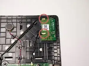
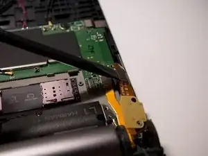
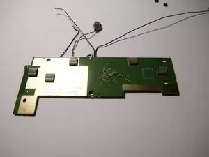
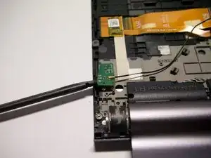
    • Unclip the antenna cable all the way.

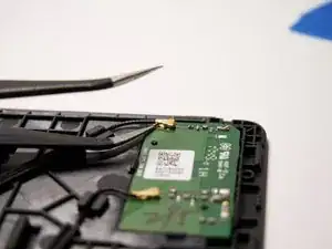
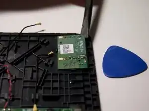
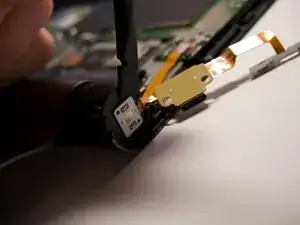
    • Gently pry the glued down Antenna board off the device using a Spudger.

    • Lift the Antenna out of the device.

  33. uXZqWMmFLfJumgDb
    uXZqWMmFLfJumgDb
    JgFXMXBx5j5fReRu
    • Remove the yellow tape covering the connector of the display ribbon cable.

    • Make sure it stays in good condition as you will need to install it in the new display later.

  34. sBLOjREjVXqKvKmB
    sBLOjREjVXqKvKmB
    AexZ1SK1nRynY2LJ
    soP63LNysKcmcQqP
    • Use a Spudger to disconnect the cable from the Display.

    • Use tweezers to lift the cable out of the device.

  35. SykDaDMP6Lo3pwPH
    SykDaDMP6Lo3pwPH
    vXTPLXaLTPpybShw
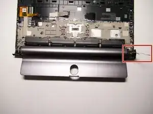
    • In this Step, be extra careful not to damage the battery cables in any way, as it is nearly impossible to find a replacement battery for this device anymore.

    • This is the trickiest step in the entire replacement guide!

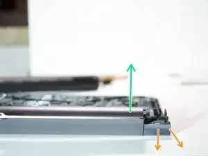
    • Pull in this direction.

    • push down and at the same time, slightly outwards.

    • You need to create a gap between the Flipstand and the plastic casing, so that you can lift the flipstand out but also fit the cables through without damaging them.

  36. yuQ3WBwncwUlTqYG
    yuQ3WBwncwUlTqYG
    aqwNwBOgrxOKqdHZ
    kYPHnoHHIgpMMKMg
    • Push the hinge out of its casing.

    • You may need to use your bare hands for this as the hinge sits very firmly in its casing.

  37. kME1jX5GQK6l62Ws
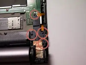
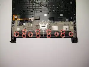
    • Remove the 12 Phillips screws securing the 4 speakers in place.

    • Unclip all 4 speaker cables.

    • Lift all 4 speakers out of the device.

    • Before putting the backplate on, check that everything is working as it should.

    • You may need to remove a few more small things depending on what replacement display you bought. Sometimes the replacement doesn't yet have the locking mechanism for the Flipstand or in some cases a few adhesive tapes are missing and need to be transferred to the new display.

Lukas

Member since: 06/02/19

517 Reputation

0 comments