Introduction

Relay failure is the most common issue with this version of the JuiceBox EVSE, most often causing a 5-beep error, but depending on firmware version, may also be a 1-beep error. Replacing it can be a simple affair, with the right tools (or a friend with the right tools), giving it many more years of service -- possibly outlasting the original due to process improvements (such as adding ferrules and tightening the lugs harder).

  1. 1rkyIwZnNRxTGguN
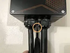
    • On most installations, the JuiceBox is held to your wall using one screw between the two cable glands. Remove this screw.

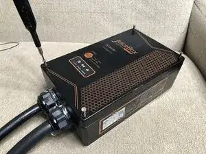
    • After removing the mounting screw, lift JuiceBox straight up (parallel to wall) to unlatch it from the wall mounting tab. If you ever sell/give away JuiceBox, keep this wall mount tab with the box!

    • If your JuiceBox is hardwired, you would instead replace these steps with simply switching-off the breaker in preparation for the relay replacement work. To remove a hardwired unit from the wall, consult an electrician.

  2. qjeTbJeZJgPKxoKV
    • Ensure the AC supply to the JuiceBox is disconnected before continuing. If the unit is plug-in, this is easy to simply ensure the box is unplugged from the NEMA 14-50 wall outlet. If hardwired, high-voltage safety training is recommended.

  3. 6HMDStAIilBiaFTF
    • Place JuiceBox on a horizontal surface for easiest work.

    • Three different types of screws were used throughout the history of JuiceBox versions.

    • Philips #2 (silver screw)

    • 2.5mm hex (rusted black screw)

    • T20h security Torx (black screw)

    • If you have a 2.5mm hex screw, be extremely careful with it - they are easy to strip and tend to bind. Use exactly a clean 2.5mm hex bit - don't substitute a Torx or other size. Press down and turn counterclockwise strongly and carefully to unscrew.

    • Once 4 screws are removed, if your box has LEDs, pay close attention to the next step before proceeding.

  4. UfUZYys5FIrWWVNJ
    UfUZYys5FIrWWVNJ
    rMfUSHP5Db5IXXem
    IOrcKtVeGLZ6DExY
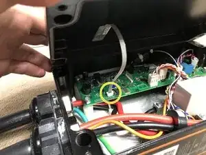
    • If your box has LEDs, slowly tilt the edge of the case away, revealing the ribbon cable connected to the board.

    • Lift the lock in the direction of the ribbon cable, and you should feel the ribbon cable release.

    • You may now remove the ribbon cable from the board, and place the lid aside.

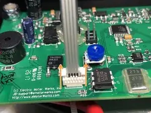
    • During reassembly, note that the ribbon cable contacts should face opposite the lock slider (as in photo). To re-insert the ribbon cable, first release the lock, insert the cable, then press the lock back down to latch it in place.

    There is a smaller blue wire that comes from the charging cable and runs to the circuit board. That blue wire is not present on replacement cables. What does it do and is it necessary?

    smithem -

    There are 4 wires essential to any cable that claims to be a J1772 charging cable. Ground (PE), line 1, line 2/neutral, and the Pilot (CP) wire. Optionally, a 5th wire may be present in some cables, Proximity (PP), and can be left out.

    If your cable only has 3 wires (line, line, ground), it's not a J1772 cable, and lord only knows how it was manufactured and sold.

    The station can't operate with just line, line, and ground, as it can't detect/signal to the car without the small Pilot (CP) wire. So yes, the blue wire is necessary and should be spliced (e.g. wire tied) to the blue (or often, orange) wire.

    Matt Falcon -

  5. o6Y12D31fxvUsVAa
    o6Y12D31fxvUsVAa
    Ab1gOvDDpZTANJtS
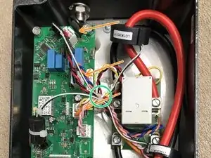
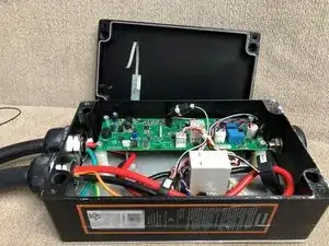
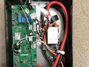
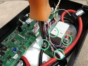
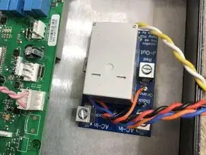
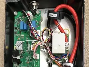
    • Unplug 3 connectors from the main board

    • Red/black - AC input to board (logic/sensing supply)

    • Orange/blue - Relay sensing (detects if relay is closed)

    • Yellow/white/orange - Relay coil (12v) and EV pilot signal

    • Clip off the zip-tie holding the wires together in a bundle

  6. aBjrxNU2jtInhPss
    aBjrxNU2jtInhPss
    TXFEUFiQEhUJHaF3
    FptUUsUBwdfUihYX
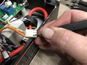
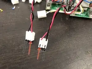
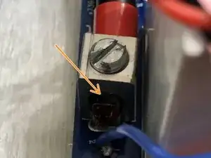
    • Use a small flat blade screwdriver (1.5mm pictured) to press the release tine of the pilot wire, while pulling snugly on the wire to pull it out of the connector.

    • This can be a fiddly process. It does take a little force to pull the connector out, but not enough to rip it out of the crimp.

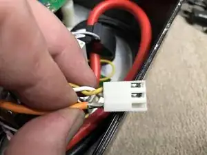
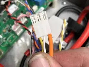
    • Feel free to go a bit ham with the screwdriver. You don't need this plastic housing - the new relay has a new housing. You do need the crimp though, so try to preserve it.

    • The pilot wire may be orange (most common) or blue (less common), but whether it's teal, auburn, heliotrope, gamboge, or rainbow colored - it's the position that matters :)

    • Once removed, find and flex the locking tab back into shape so it'll lock on the new connector.

    I took a large paper clip and pounded an end flat with a hammer. It made a tool just the right size to release the tab.

    Victor Weers -

  7. dmJ5fZ5AoNhAapP1
    dmJ5fZ5AoNhAapP1
    F2aiVKyJSdLCTt1V
    4CeTXoXoZqoOSdLw
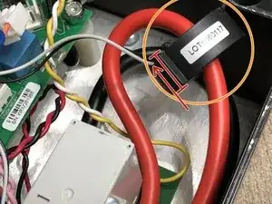
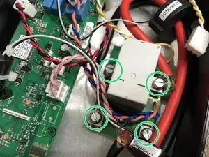
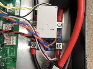
    • Observe and note the direction of the large current sensor around the red lead of the charging cable. The direction is programmed into the box at manufacture time - flipping it will cause your energy reporting to be ... backwards.

    • To simplify keeping this straight, you can simply slide the sensor back down the line (towards output cable gland) while working on the relay, without needing to remove the sensor.

    • Use a flat-head screwdriver (7mm used here) to unscrew the 4 screw terminals of the relay board.

    • Remove the 4 wires and bend aside.

  8. QBU3jJYiwYBHP1Tr
    QBU3jJYiwYBHP1Tr
    Q3tmXx1akGoktriF
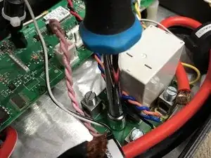
    • Remove the two 11/32" hex nuts that secure the relay board to the chassis.

    • Lift the relay and board out of the chassis.

  9. 3G6EQKKIqt4ykRFV
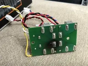
    • It's been discovered that different ages of JuiceBoxes have the red/black pins in different positions (nearly 50/50%).

    • Using the same technique as removing the pilot wire in an earlier step, compare your new replacement relay and your original relay, and swap the red/black pins as needed.

    • The JuiceBox will work without doing this, but may report reverse energy. If you see erroneous energy reporting in the app (e.g. inverted power graphs, weird stats), flipping the red/black should fix it.

  10. SxxvBnVAH4ViNHFp
    SxxvBnVAH4ViNHFp
    swOwg5gLZkwkmZUQ
    PoQYFIldUFQgLFLa
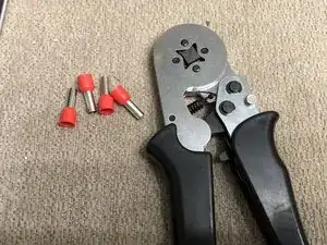
    • Crimping ferrules onto the wire ends was an improvement added to later production JuiceBoxes. You can add this layer of protection yourself by crimping ferrules to the wire ends before installing a new relay.

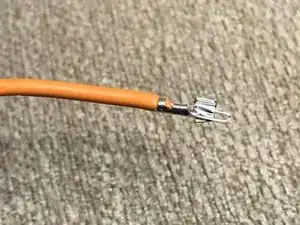
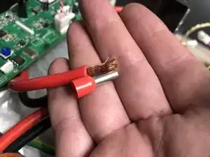
    • Strip a bit more insulation off the wire strand, to allow the wire to fill the full ferrule.

    • Insert the ferrule on the wire end, while stuffing the wire insulation into the plastic collar so that the copper strands are just poking up to the end of the crimp.

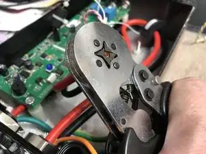
    • Insert ferrule (now with wire) into the crimper (but don't crimp the plastic collar!), and squeeze to crimp - these crimpers are self-adjusting to wire size.

    • Repeat for all 4 wires.

  11. wbssDjt4aJpSIluT
    • Guide the new relay onto the posts - it may be a tighter fit, but just... make it go. Observe the direction of "AC-In" which should be at the bottom - as pictured, text upside down.

    • Reinstall the two 11/32" nuts and tighten securely.

    My relay board has the AC in on the bottom but the text is right side up

    Sevak Kazaryan -

  12. 1M5qAiBjpd2Mtxas
    1M5qAiBjpd2Mtxas
    qdfCONmIOhaK6Fst
    • Open up the screw terminals of the new relay fully, so you can fit the wires in without fraying - or fit the new ferrules.

    • Insert the wires into the terminals per the large silkscreen text adjacent to the terminals (note the red/black don't match the small wires).

    • Again, note the direction of the large current sensor around the red line - go back and check your notes if it matches your original.

    • Using a medium-large flat blade screwdriver, practice Turbo Gorilla Grip on all 4 screw terminals. Tighten it almost 'til you think it'll break, then a little further. Screw it back and forth a couple times and see if you can get even more crush out of it. The goal is to fully flatten the strands so it won't settle in the future.

    • (This is less important if you've added ferrules, which already provide a good amount of crush to the wires! But still, give 'er a good crank!)

    I detached the ribbon cable from the casing, how I get a new one to replaced it? Right now the charger is working, but no lights are on at the front panel.

    Help JB -

    If you broke the LED flex panel while taking it apart (ripped, detached, otherwise doesn't work), then that's why I also made a replacement LED strip years ago and still sell it today :) https://www.ebay.com/itm/265622323152 or search "juicebox replacement led strip" on eBay.

    Matt Falcon -

  13. XC1i2fS1MLCmdM34
    XC1i2fS1MLCmdM34
    hPuV3UQ2YLMYUoyt
    • Slide the original pilot wire into the empty position of the new relay's yellow/white connector. It should click and lock into place.

    • Reconnect all 3 connectors to the board.

    • Red/black at the top

    • Orange/blue at the middle

    • Yellow/white/pilot (orange or blue commonly) at the bottom

    • Note: we haven't touched the pink (GFCI test) connector, but technically that's the bottom connector. :)

    Perfect guidance.

    Eugene Patterson -

    My pilot wire was blue but it was the biggest wire in any of the connectors.

    Geoffrey Martin -

    Worked great! Everything worked as expected. I had one small freak-out with the ribbon cable at the start because it just slipped out. But it turns out that is how it disconnects (the connector stays put on the board, the ribbon slides in and out). Plugged back in - the error beep was gone, and LEDs came on.

    Zach Powers -

    • Follow reverse steps for disconnecting the front panel LED, the front cover screws, and the wall mounting, for reassembly.

    Just want to add my agreement that this worked perfectly. I have no experience pulling wires from connectors, so pulling the pilot wire was the longest step and I absolutely destroyed the old connector. But it worked and was up and charging my car in right around an hour. Thanks Matt!!

    Wireless8952 -

    Worked for us, too. Since we don't have any ISO electrical repair facility to insure quality after repair, is there a potential issue with insurance if any fire or smoke damage were to be linked back to a repaired JuiceBox EVSE? Seems the UL certification is no longer good after repair even with an OEM relay and PCB. We are using the repaired units for educational use at our Technical College due to this concern.

    M R Smith -

    I think that's a problem with repair in general. Hard to maintain a chain of trust-in-workmanship in any economical way, so it's just generally not done, and it causes tons of waste where just a $10 part was really needed to fix a $1000 device (in some device repairs).

    Being as the JuiceBox is in a metal enclosure, and that metal enclosure has withstood many full-fire burnouts inside the box, the worst case has already been tested, and there is no plausible way for a repaired part to cause a fire or smoke damage. If it fails, it'll destroy the box and stop there, all contained inside the box (trust me, I've seen some... stuff - but I've not yet seen a replacement relay ever burn out). I think any agency would have a truly difficult time trying to pin the blame on a repaired box... but due to the difficulty in proving that, it remains a challenge for bureaucratic orgs.

    Matt Falcon -

Conclusion

To reassemble your device, follow these instructions in reverse order.

Matt Falcon

Member since: 09/05/15

2616 Reputation

43 comments

Well, this is great. But for the problem that the ebay relay is not available.........

David Hermanns -

Wow! 😅 Lots of people want these relays suddenly today... 😅

In general, if it's out of stock, just check back next Monday. I only list what I've built, and since they're all (at least today) soldered & assembled by hand, there's a bit of a throttle. I'm working on having them made instead...

But for now they're built in batches every weekend!

Matt Falcon -

Thanks Matt. Instructions were super easy to follow. The tip on the part was also helpful. Saved one charger from e-waste and me from buying a new one. The hardest part was getting that trigger wire out of the connector and back in the new one. Needed a little adjustment to get to stay in the new connector.

Geoffrey Martin -

Matt, I want to thank you for posting this repair. It was actually very easy. Your instructions were right on. I appreciate you taking the time to write this up. It saved me from buying a new charger. Thanks again. PG

Peter Gonzalez -

Thank you for this guide…are there a relay available for purchase?

Kaala Training Chair -

There will be - just a gap in stock right now that will be filled quite soon. I finally got an ETA, and it'll be available by the end of the week. It's not visible on eBay (via the iFixit link which leads to a search) as it's out of stock right now, but it's generally available here: https://www.ebay.com/itm/265225261067

Matt Falcon -

Just ordered it via your link….thank you!

Kaala Training Chair -

Installed and working….thank you….

Kaala Training Chair -

Installed and EVSE unit is back from the dead! Instructions were very easy to follow. Thank you, Matt!

Lee -

Thank you Matt for making this relay board available as well as the excellent instruction. I completed the installation without an issue but did notice that the control wire in my 2019 Juice Box was blue rather than the orange in the photo.

Tim Weber

Tim Weber -

Just ordered the replacement relay but am looking for more details of the ferrules and crimp tool. Also, what is "Turbo Gorilla Grip"?

Cyber Vinnie -

Turbo Gorilla Grip is just the name of the concept that's explained by the instructions ;) Crank the screws down hard!

Ferrules - optional, but click the link in the Tools section of the guide here - that'll take you to some Amazon results. Just look for the kit that has the large red size (usually the biggest one in the kit).

Matt Falcon -

Thanks Matt! I figured that's what you meant by gorilla grip, but the capitalization made me have second thoughts, as if it was some sort of adhesive. Perhaps this allows me to justify buying a new crimp tool!

Cyber Vinnie -

Het Matt, your replacement arrived today and it probably took me longer to find my T20 security Torx than it took to replace the relay board! On the bottom of the receipt you wrote, "Thanks for repairing instead of replacing", but I have to say to thank YOU for making the part so I COULD repair it instead of replace it!!!

Cyber Vinnie -

Having this issue on and off for a few months now. I'd like to fix it; any chance you could put a few more parts up on eBay?

Blue Eyes Designs -

I was wondering, would this guide (and relay part) work on the non-pro version. Everything look the same, but wanted to check. Thanks

Alexandre Fortin -

Just finished doing the repair. Everything work fine. Did have problem reinserting the pilot. But I do work with the non pro. Thanks

Alexandre Fortin -

Thanks for the guide!

I replaced the LED strip and added ferrules to my juicebox pro 40.

If you are having issues first have your electrician check the wires are tight in the EVSE circuit breaker and the rest of the panel (every few years), they should be very tight.

Glim1000 -

Excellent guide and an honorable business. Thank you, Matt. My charger was configured differently at the LED strip connection- it took an extra pair of hands to get it reconnected, and great tip on going ape removing the pilot wire. My old relay switch didn't appear to be fried- if you're interested I can ship it back for reuse to someone else if you want to repair it.

wwguide -

I detached the ribbon cable from the casing, how I get a new one to replaced it? Right now the charger is working, but no lights are on at the front panel. Please help.

Help JB -

relay

Look at the top of this guide at Parts

Toon Konings -

Thank you so much. The charger is working again after the relay replacement. However, the middle blue Wifi light is not lighting up and it appears the Wifi no longer sees the charger. Model JuiceBox 40 Pro (2019). The Wifi has always worked in the past. Any insights on getting the repaired charger connected back to the wifi? Thanks again. Peace

Joseph Keays -

Sounds like an LED strip issue. The Network (blue) LED will always flash or be on - the firmware does not have a state of "off". You can get a replacement LED strip on eBay. Under the hood, you need to leave the box powered up for several minutes (5 or so), for setup mode to time out, and for it to go online.

From there, you have to do the song-and-dance routine with spinning in a circle 5 times, hold the phone up, hold it to your chest, turn it upside down, do a skip-hop, install 3 different versions of the app, 2 accounts, call support, and only then, you can maybe get access to your box on the correct network.

That's a joke of course, but the Enel app SUCKS these days and is incredibly unreliable/user-hostile. The most common way to get it to work is just to plug it in and check back the next morning. Never expect it to come up immediately.

Matt Falcon -

This is by no means a criticism since your relay and instructions have saved me thousands...after the box is now back up and working thanks to you, I am only pulling 9.2 to 9.4 kwh compared to the 9.6kwh I used to pull prior to the box/relay failing. Note 240v*40amps = 9.6kw. Can you help explain why I am drawing a little less. Again, I am not complaining, I just like the math and the theories behind it all. Thanks again. Peace

Joseph Keays -

Important distinction - kW from kWh - kW is a rate of speed (how fast you're charging, rated speed of a charger/station, etc = Watts), while kWh is a measure of how much you have charged (energy/range added, capacity of a battery, etc = Watt-hours, "a watt used for an hour"). "k" for kilo = thousand :)

Hard to say why you'd be seeing less kW after switching the relay. It just connects the line to the car. The metering CT should be in the correct direction (you'll know if the app shows 0 or negative kWh in a session). Is the kW you're seeing displayed in the car, or in the app? It's a bit odd a discrepancy, for sure. Hard to really pin down what the cause is, because the box is still signaling the same max 40 amps as before (unless the settings were changed, e.g. settings page set to 39a). Knowing more details about where you're seeing the measurement may help!

Matt Falcon -

Just FYI, after opening up the Juicebox, I gave several firm taps with a screwdriver handle to the relay, and after closing the unit up, it's now working again. We'll see how long this lasts, but for now I'm back up and running.

Hal Forman -

Thanks. I will double triple check all of my settings for the JuiceBox App. Peace

Joseph Keays -

I bought just the relay, desoldered and removed the old one, soldered in the new one. These instructions were very helpful and everything works (for now) but I made a mess of the old board. Next time I'm just buying your replacement board! Thanks Matt!

jonathan6 -

<< The-WHAT.png >>

I have replaced a few relays on boards over the years, but it was... most certainly not something I wanted to repeat. I admire your dedication. That is no easy task. haha. Congrats!

Matt Falcon -

Bought part on ebay, received and installed in ~1hr. Great instructions and money well spent. Hopefully the charger lasts another 5 years. THANK YOU.

Hardest part for me was removing the security screws of the case. 3 corners were fine but 1 was oddly sized and I ended up stripping the head. Had to use a dremel to notch it and a flathead screwdriver to remove. It scratched up the case a bit but I could care less about how this thing looks.

michaelychien -

We got the relay via ebay and used the great tutorial to switch it out which worked without any problems. The unit turned on again as I hoped but had lost connection to the internet/app with the blue LED light slowly blinking for hours. We rebooted the unit a couple of times which did not change anything. We tried to reconnect the unit via the app which did not work, we always came back to the screen telling us that the unit was offline. We then unpaired the unit in the app and tried to add the box again, that process always aborted and we came back to the add a box screen. We tried using an Android phone and an Apple IPad, both approaches did not work, we could not reconnect the box. I assume that the electronics got damaged when switching out the relay, looks like we will still need to buy a new charger.

AW4 -

You don't need to be connected to WiFi for charging to work. There has been a network issue with Enel (who seems to be... unresponsive to issues, to put it one way) and certain models of JuiceBox as of late. My own box, as well as many others, have lost connection to their cloud, which makes them unusable in the app. It shouldn't affect charging, though. You can still use the box, but their... dubious app functionality will no longer be there.

There is effort towards making a local replacement for the Enel services, though, if you look up "juicepassproxy" - it's a bit immature and not a drop-in replacement though, as it needs more developer help to get it over the finish line towards being a full and proper replacement for app scheduling/stats/control. It's meant to work with Home Assistant as a home server - HA is a very broad home-automation system to take control back from the cloud for many devices.

I worry this may be the end for the JuiceNet app...

Matt Falcon -

Thanks Matt. After trying some programming we got the box connected to our router and the chat function of Enel managed to get the app up and running again for us. Not sure what they did remotely but it works for the moment.

AW4 -

Hi Matt: I just received the relay replacement switch for my JuiceBox Pro 40, purchased April/2018. I followed your detailed instruction and attempted to power I up the unit. After a few seconds, the WiFi indicator blinking rapidly, however, the power indicator would not illuminate. I verified all the removed connectors, and 4 power wires, but I am unsure why the power lite is off on the strip. All three lights were working prior to relay error code (5 heaps). Can you please advise? I have not hooked the charging cable to a vehicle, until i resolve this issue. Thank you.

Brian -

The Network (blue) LED will never flash on its own (without the power LED) under the software control. That just means your LED strip is damaged/broken (or incompletely/sideways/backwards inserted). It's fairly delicate, and being ripped out of the socket (or peeled off the lid) can easily break the traces, leading to erratic LED indications.

I have a replacement (well, a reproduction - built differently, but fits and works) LED strip available on eBay along-side the replacement relay, if you want.

If not, the box would still work normally. The fact that the power LED doesn't illuminate means it's 100% a fault of the indicator LED board itself, not something the board/firmware would ever indicate on its own.

Matt Falcon -

Thank you Matt, you should know that the charger does charge my vehicle and the WiFi did pair with my phone and the internet without a problem. Is it possible that I inverted the LED cable? So, correctly removing it, and reinserting it (flipping it around) the other way could in fact resolve this problem? Your very good instruction did not address the cable as to which way it should be reinserted into the clip, or if the cable only goes in ONE WAY only to correctly operate. I did pull out magnifying glass to see if I could see the terminal leads on the cable but I wasn’t sure which were the smooth metallic leads, and should they be inserted facing to the left or right of the connector to make a good contact. Yes, if this does not, I will certainly purchase a replacement LED cable.

Nevertheless, all readers should know that the replacement relay switch works perfectly & the step-by-step instructions were extremely helpful. Perhaps, a tutorial video on the install should be created to aid in this process.

Brian -

It could be flipped, yeah. In the original cable, it goes into the board without any flip from the lid to the board. On the replacement, it's flipped (so it flips 180 from the lid to the board). So with yours, start with the cable unplugged and relaxed, see how it rests, and then take the connector and plug it into the board without twisting it.

As long as you never accidentally pulled off the lid and yanked the cable out, and if you haven't pulled the connector out without unlocking it (which can often scratch the delicate contacts and break connectivity), it should work. If you (or someone else reading) had, accidentally pulled out the connector without unlocking it, and scratched the conductive material off the cable, you can sometimes get a second life out of it by carefully trimming-off about 1mm off the tip of the connector, giving it a new contact area when fully inserted & locked.

Thanks for the compliments :) It's not likely I'd be one to make a video though, but others may be on YouTube :)

Matt Falcon -

I have the white/greyish plastic case model JuiceBox40 with front LEDs (manufactured late 2020). Would this relay work with the generation JuiceBox I have?

KMILL23 -

No, unfortunately that model of JuiceBox is not one I support (partly out of protest of Enel). Sorry to catch you up in that, but those are just cooked if their relays burn out.

Matt Falcon -

Dang, Matt. I was hopeful your solution would work for me. I'm learning what you are telling KenyG below here. Enel tech support gave me the relay # and it matched the photo on your eBay listing, so I got encouraged that it might be the right fit for this generation, too.

As an engineer and an avid DIYer, it PAINS me to think that this thing is just trash now. :(

KMILL23 -

Hey, that J1772 cable/handle still has value! Can't repair those handles, so if anyone has a damaged handle, they've gotta replace the whole cable. So, that big ole' cable can still go to some use!

Matt Falcon -

Where can I buy just the relay without the board? My board is fine but the relay sometimes sticking.

KenyG -

Digi-Key. AZSR250-2AE-12D is the model of the relay.

You are going to quickly discover why the board and the relay are sold as one assembled part ;)

Or slowly, depending on how quickly you discover how hard the soldering is to do with current-carrying, heat-sinking material that large!

Matt Falcon -