Introduction

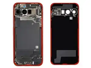
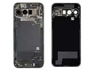
This guide shows how to remove the interconnect cables from your Google Pixel 9 Pro XL.

  1. iywHWnu1SHN2uQYh
    iywHWnu1SHN2uQYh
    DDba2IYvihnIWjP6
    • Let your Pixel's battery drain below 25% before starting this repair. A charged lithium‑ion battery may catch fire if damaged.

    • Unplug all cables and completely power down your phone.

  2. r4ALN1nNrl6VZPRt
    r4ALN1nNrl6VZPRt
    qQcMm3UWVCfl6HRf
    EjiIYYrMD66sFdQJ
    • Adhesive secures the perimeter of the rear cover to the frame.

    • When separating the adhesive, don't insert your tool more than 3 mm under the rear cover to avoid damaging the internal components.

    • Measure 3 mm from the tip and mark your opening pick with a permanent marker. Alternatively, you can tape a coin to a pick 3 mm from the tip.

  3. OaiCwDY1lk41A6Xf
    OaiCwDY1lk41A6Xf
    kptZ6ACd6oUwu3FY
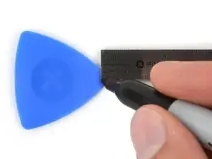
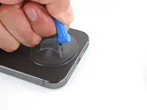
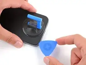
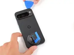
    • Attach a suction handle to the bottom edge of the rear cover, as close to the edge as possible.

  4. yw1EJlOiABskBdKL
    yw1EJlOiABskBdKL
    MxJdqYHajYtvTpSA
    RvEdZYgHwdnXfwaC
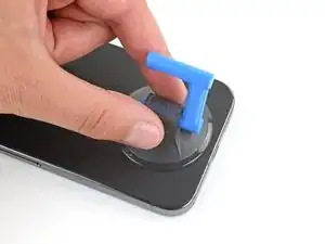
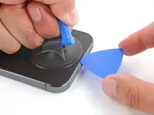
    • Pull up on the suction handle with strong, steady force to create a small gap under the rear cover.

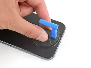
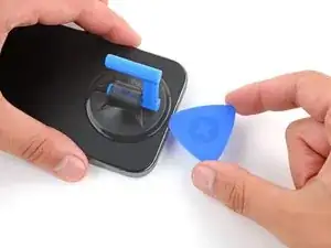
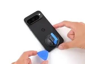
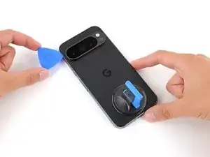
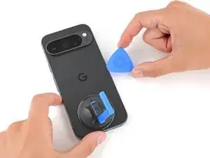
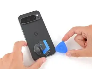
    • Insert the tip of an opening pick in the gap.

  5. HkyuyubdI1H2AhKb
    HkyuyubdI1H2AhKb
    HILCAWMvJaJoS2do
    DTIPQw3bSMMYWUqI
    • Slide your opening along the bottom edge to separate the adhesive securing it.

    • Remember: don't insert the opening pick deeper than 3 mm.

  6. 2oRhYpMIYHSnHhvr
    2oRhYpMIYHSnHhvr
    ByXnLwODUBeEsTgO
    y53cfD3QiL45NIBY
    • Slide your opening pick up the left edge and along the top edge to separate the adhesive.

  7. ePjwYS6ZGdYRDf4q
    ePjwYS6ZGdYRDf4q
    uKjPnqP535TdUNLG
    Mt6r5HGxaAyYrvKR
    • Slide your pick down the right edge to separate the remaining adhesive.

  8. iZIoft16hOEIhGno
    iZIoft16hOEIhGno
    qCKgjJv6ub1RJ2OS
    kBrnVdRlMxKIKhkF
    • Don't try to fully remove the rear cover yet, as a ribbon cable on the right edge connects it to the phone.

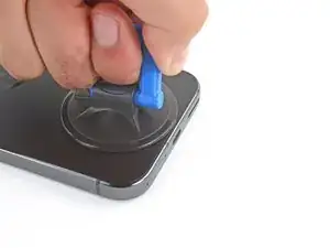
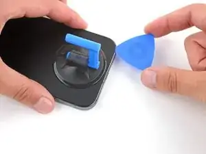
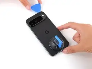
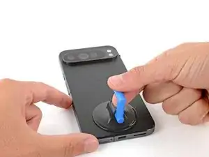
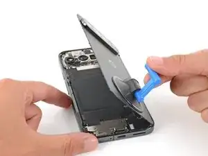
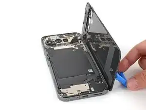
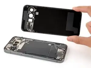
    • Use the suction handle to lift the left edge of the rear cover and swing it over the right edge, like opening the cover of a book.

    • If you're having trouble, check the perimeter for any remaining adhesive and use your opening pick to separate it.

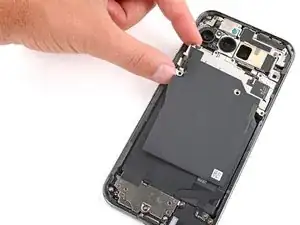
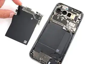
    • Prop up the rear cover with the suction handle so you can access the ribbon cable near the top right corner.

  9. LolmXX3FYteqgZlD
    LolmXX3FYteqgZlD
    XPTAYqElw2j2ljWY
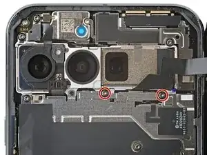
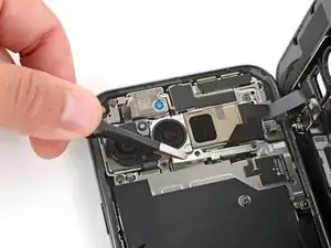
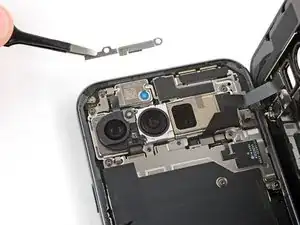
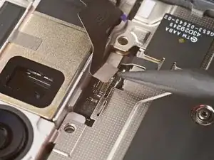
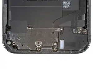
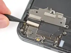
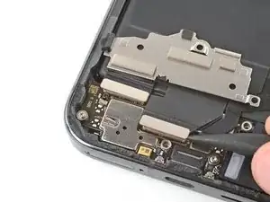
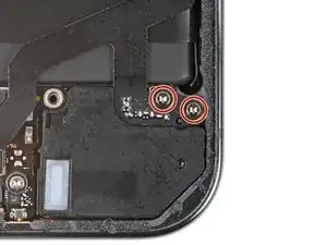
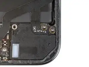
    • Use a Torx Plus 3IP screwdriver to remove the two 5.2 mm‑long screws securing the cable cover.

  10. GpQmenOfFkrnfJCI
    GpQmenOfFkrnfJCI
    hUK5o6MKZ2aJGrre
    • Use tweezers or your fingers to remove the cable cover.

  11. b1EHtOWOIkCsYJMi
    b1EHtOWOIkCsYJMi
    rZoWbFwTDOTPfxi5
    Q313qlo1iCSCRGMa
    • Use the point of a spudger to pry up and disconnect the rear cover press connector.

  12. EbvwhUMPfph3Htsm
    • Remove the rear cover.

    • During reassembly, follow this guide to apply new adhesive and install your back cover.

  13. exgsvnvwwRxlnjnS
    exgsvnvwwRxlnjnS
    UNKqwfS2DtvyOJ6r
    unbflEvIiBNR2j5S
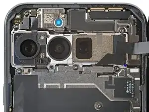
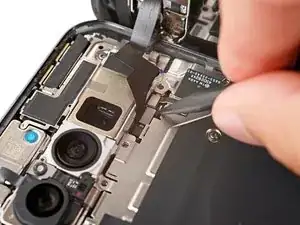
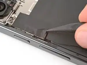
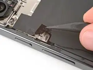
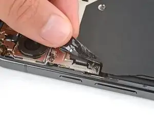
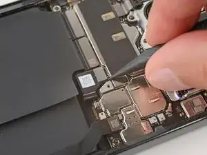
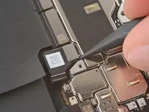
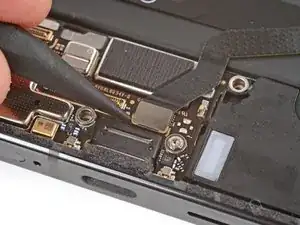
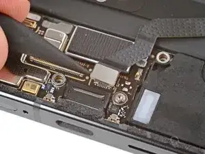
    • Use the tip of a spudger and your fingers to peel up the piece of tape near the left edge of your phone, enough that you can access the bracket and screws underneath.

    • You can completely remove the tape if you want, but be sure to keep it for reassembly.

  14. JQSwpO5iop3GrHI1
    JQSwpO5iop3GrHI1
    CYH2DsKUWUvWOQhd
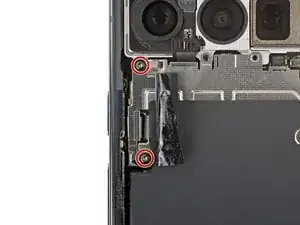
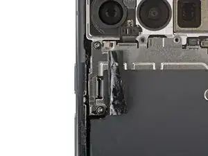
    • Use a Torx Plus 3IP screwdriver to remove the two 5.2 mm‑long screws securing the wireless charging cable cover.

  15. 3DUgLvA6lUX6SGOY
    3DUgLvA6lUX6SGOY
    pJFsaLIySdvKB2VS
    • Use tweezers or your fingers to remove the cover.

  16. IpRfIMQxLPM6SN4Z
    IpRfIMQxLPM6SN4Z
    paeHdcO533rWjeD6
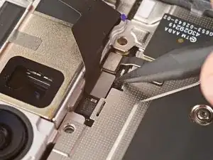
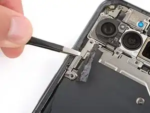
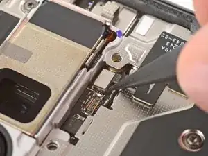
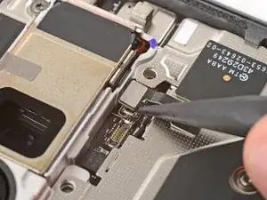
    • Use the tip of an opening pick to pry up and disconnect the wireless charging press‑connector.

  17. wVNpd4PYaEeSAHwI
    wVNpd4PYaEeSAHwI
    kCXPJjLNTQHQnSnR
    K4yvBVgyfaGnDctv
    • Use the point of a spudger to pry up and disconnect the ultra‑wideband press connector.

  18. t3ZXfUsVF5LrfJEs
    t3ZXfUsVF5LrfJEs
    1CbgATKgZMteXhyu
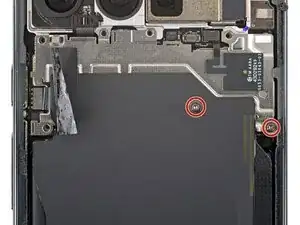
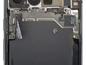
    • Use a Torx Plus 3IP screwdriver to remove the two 2.2 mm‑long screw securing the wireless charging assembly.

  19. NsYVxPKZDZ5MyKPC
    NsYVxPKZDZ5MyKPC
    faVGQOoglaxpDJv3
    • Remove the wireless charging assembly.

  20. QHEBZXva4kajIlAJ
    QHEBZXva4kajIlAJ
    XP1HwGSiWQNXVOWE
    dZpKJIysjNyE1M3N
    • Use a spudger to pry up and disconnect the battery press connector.

  21. SMvvYlOmBQ2Fsp3H
    SMvvYlOmBQ2Fsp3H
    RcpuoOEbBYDEoCRp
    rfSsKXvHYMgpkGkt
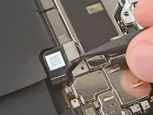
    • Use a spudger to pry up and disconnect the three remaining press connectors along the bottom edge of the logic board—two larger press connectors near the center and one smaller one on the bottom right corner.

  22. epTNT41vWS4DTG2s
    epTNT41vWS4DTG2s
    vYqVMdtRTkKcScRk
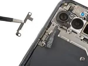
    • Use a Torx Plus 3IP screwdriver to remove the two 4.2 mm‑long screws securing the charging board cover.

  23. pSUaPKXMb2STSnUE
    pSUaPKXMb2STSnUE
    vSTdVGtWPFbhLbDL
    VUdQPQFgVypOdvOG
    • Don't try to fully remove the cover, as a piece of tape secures it to the interconnect cable.

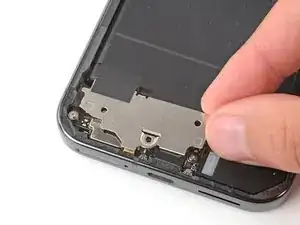
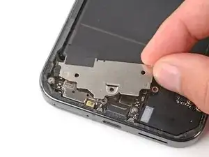
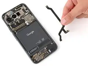
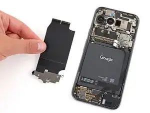
    • Use your fingers to pull the right edge of the charging board cover towards the top of your phone to unclip the left side of the cover.

    • Flip the cover away from the charging board so you can access its press connectors.

  24. b3xAQrGndOZZcSXV
    b3xAQrGndOZZcSXV
    GFQekdTMnWSNuZAi
    YitFTwBxFCT3DjLY
    • Be very careful not to damage any of the small, surface‑mounted components on the charging board.

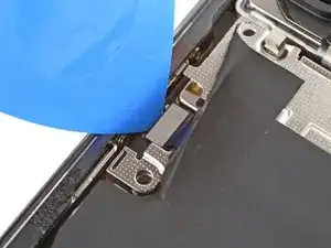
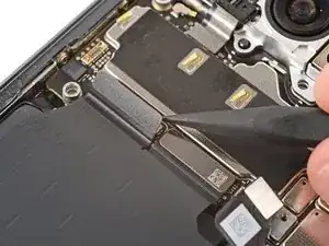
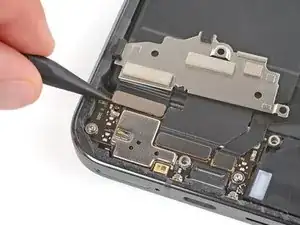
    • Use the point of a spudger to pry up and disconnect the two larger press connectors on the top edge of the charging board.

  25. HgCqlSytZLpCQVkU
    • Remove the left interconnect cable.

  26. AoLmfKVLSDTxmwTC
    AoLmfKVLSDTxmwTC
    NtIHy6yH1RghGF6q
    • Be very careful not to damage any of the small, surface‑mounted components on the charging board.

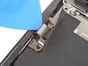
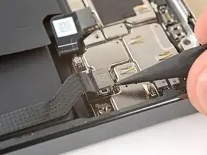
    • Use the point of a spudger to pry up and disconnect the remaining press connector on the right edge of the charging board.

  27. fntXv11MDt6YYB1k
    fntXv11MDt6YYB1k
    MmXqtEqxyPJDENpR
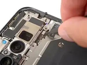
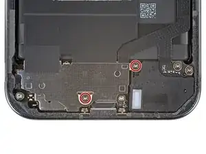
    • Use a Torx Plus 3IP screwdriver to remove the two 4.2 mm‑long screws securing the bottom of the right interconnect cable.

  28. XnyhHd1JDHVEdXBe
    • Remove the right interconnect cable.

Spencer Day

Member since: 14/09/22

88286 Reputation

0 comments